
Related Manuals for AR 1000W1000G


Summary of Contents for AR 1000W1000G
- Page 1 Operating and Service Manual 1000W1000G Model 10048081 Part Number Serial Number 160 School House Road, Souderton, PA 18964 • 215-723-8181 • Fax 866-859-0582 • www.arworld.us...
- Page 3 REGULATION (EC) 1907/2006 OF THE EUROPEAN PARLIAMENT AND OF THE COUNCIL of 18 December 2006 concerning the Registration, Evaluation, Authorization and Restriction of Substances of Very High Concern Chemicals (SVHC) Supporting documentation is held by AR RF/Microwave Instrumentation’s Quality department in Pennsylvania, United States. Place of issue:...
- Page 5 Instructions for European EMC Conformity WARNING It is the responsibility of the user of this equipment to provide electromagnetic shielding, filtering and isolation which is necessary for EMC compliance to Directive 2014/30/EU. The equipment must therefore be operated in a shielded area which provides a sufficient level of attenuation to meet the radiated emissions and immunity specifications.
- Page 7 The caution symbol denotes a potential hazard. Attention must be given to the statement to prevent Your AR equipment may have more than one power supply cable. Use damage, destruction, or harm. only approved power cable(s). If you have not been provided with a Dangerous voltages are present.
- Page 8 EQUIPMENT CONTAINING LASERS risk of serious injury due to unsafe AR Field Probes (FL/PL Series) and Field Analyzers (FA product handling should be a fundamental Series) are Class 1 laser products containing embedded consideration every user.
- Page 9 Zur Vermeidung von Personen- oder Sachschäden gilt BEVOR SIE DAS GERÄT ANSCHLIESSEN es, die Hinweise zu beachten. Ihre AR-Ausrüstung hat möglicherweise mehr als ein Stromversorgungskabel. Gefährliche elektrische Spannungen sind vorhanden. Verwenden Sie nur zugelassene Stromkabel. Falls Sie kein Stromkabel oder Höchste Vorsicht ist geboten.
- Page 10 Die meisten Geräte müssen während des Versands, der Montage und des Gebrauchs LASER-INFORMATION transportiert werden. Jeder Nutzer sollte sich AR - Feldsonden (FL/PL-Serie) und Feldanalysatoren (FA-Serie) über das Risiko von schweren Verletzungen sind Laserprodukte der Klasse 1 mit eingebetteten Klasse-4- durch unsachgemäße...
- Page 11 électrode de mise à la Votre équipement AR peut disposer de plus d’un câble d’alimentation terre de protection. électrique. Utilisez uniquement un ou des câbles d’alimentation approuves.
- Page 12 éliminer le risque injustifié de blessures causées par le levage est fournie par les méthodes de travail de NIOSH (publication Les sondes de champ AR (série FL/PL) et les analyseurs de n° 94-110) disponibles sur : champ (série FA) sont des produits laser de classe 1 contenant des lasers intégrés de classe 4.
- Page 13 Er zijn gevaarlijke elektrische spanningen aanwezig. Wees uiterst voorzichtig. VOOR HET OPZETTEN VAN DE STROOM Uw AR-apparatuur kan meer dan een netvoedingskabel bezitten. Gebruik alleen goedgekeurde netvoedingskabel(s). Koopt een Wijst op een terminal aan die bedoeld is voor aansluiting netvoedingskabel die is goedgekeurd voor gebruik in uw land als u...
- Page 14 APPARAAT DAT LASERS BEVAT distributie, de assemblage en het gebruik moeten worden behandeld, moet het risico AR-terreinsondes (FL/PL-serie) en terreinanalysatoren (FA- op ernstig letsel als gevolg van een serie) zijn laserproducten van klasse 1 met ingesloten onveilige behandeling van het product een klasse 4-lasers.
-
Page 15: Table Of Contents
TABLE OF CONTENTS TABLE OF CONTENTS ....................iii GENERAL INFORMATION ................1 General Description ....................1 Specifications ......................1 Power Supplies ....................... 1 Protection Circuits ....................2 Installation ......................2 1.5.1 Location ........................2 1.5.2 Power ........................3 OPERATING INSTRUCTIONS ................ 9 General ........................ - Page 16 Model 1000W1000G 2.6.6.12 RF Gain ......................26 2.6.6.13 Faults (1000W1000G) ................... 26 2.6.6.14 Operating Hours (RF On) ................27 2.6.6.15 Operating Hours (Power On) ................. 27 2.6.6.16 AC Power-On Defaults .................. 28 THEORY OF OPERATION ................29 Introduction ......................29 RF Amplifier Operation (Schematic 10046373) ..........
- Page 17 Typical 12-Way Combiner Return and Insertion Loss ......... 41 Typical A2 Driver Module Response ..............42 Typical A1 Pre-Amplifier Response ..............42 4-10 1000W1000G, Right Side, Modules A6-A7 and A10-A13 ......... 43 4-11 1000W1000G, Left Side, Modules A14-A15 and A18-A21 ........ 44 4-12 Molex Connectors ....................
-
Page 19: General Information
(EMI) susceptibility testing, as well as usage as a driver for frequency multipliers and high-power amplifiers. The Model 1000W1000G can be operated locally by using the unit’s front panel controls, or remotely by using the unit’s IEEE-488, RS-232 interface, USB, or Ethernet interface. -
Page 20: Protection Circuits
Select an operating location that will permit air to circulate freely around the amplifier’s cabinet. The Model 1000W1000G utilizes air cooling and should be located where the normal flow of air into or exiting from the unit will not be restricted, diverted, or re-circulated through the unit itself; in particular, the flow of warm air exiting the rear of the amplifier should not be impeded. - Page 21 Model 1000W1000G 1.5.2 Power The Model 1000W1000G is designed to operate using AC primary power of 200–240 Volts Alternating Current (VAC), 50–60 Hz single phase, 3300 watts maximum. CAUTION: Dangerous voltages are present in the Model 1000W1000G whenever the unit is plugged into an AC outlet. Always disconnect the unit from the main power line when servicing it.
- Page 22 Model 1000W1000G Rev A...
-
Page 23: Power
Specifications Features 1000W1000G The Model 1000W1000G is a solid-state, self- temperature or power supply fault has oc- contained, air-cooled, broadband amplifier curred. The unit can be returned to operate 1000 watts CW designed for applications where instantaneous when the condition has been cleared. - Page 24 NOISE FIGURE: 8 dB maximum; 6 dB typical HARMONIC DISTORTION: Minus 20 dBc maximum at 900 watts; minus 20 dBc typical at 1000 watts SPURIOUS: Minus 73 dBc typical Ordering Options Contact your AR RF/Microwave Instrumentation Sales Associate for specific model configuration pricing.
- Page 25 Page 3 Graphs 1000W1000G 1000 watts CW 80MHz–1000MHz...
- Page 26 Page 4 Graphs 1000W1000G 1000 watts CW 80MHz–1000MHz...
- Page 27 Page 5 Envelope Drawing 1000W1000G 1000 watts CW 80MHz–1000MHz To order AR Products, call 215.723.8181. For an applications engineer call:800.933.8181. Direct to Service call: 215.723.0275 or email: service@arworld.us For Faxing Orders:866.859.0582 (Orders Only Please) info@arworld.us Approved for public release by AR RF/Microwave Instrumentation...
-
Page 29: Operating Instructions
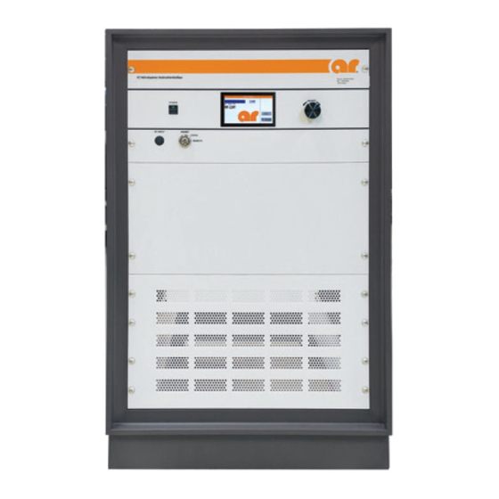
RF stages, when the chassis temperature reaches approximately 70°C. Normal operation can be resumed after the chassis temperature drops below 70° C. CONTROL AND INDICATOR FUNCTIONS The Model 1000W1000G’s front panel is shown in Figure 2-1; the unit’s rear panel features are detailed in Figure 2-2. 2.2.1... -
Page 30: Power Switch
Model 1000W1000G 2.2.2 POWER Switch The momentary POWER switch turns the main power to the amplifier on and off. The status of the green light-emitting diode (LED) in the switch indicates whether the amplifier’s power is on or off. The main power supply fans are active when power is on. -
Page 31: Main Power
Model 1000W1000G 2.2.3 Main Power The Main Power circuit breaker and the RF output (N female) are located on the rear panel of the amplifier. Figure 2-2. Rear Panel Features 2.2.4 RF ON/OFF The RF ON/OFF touch screen button toggles the amplifier from a Standby to an Operate mode. The status of the function is indicated on the display as RF ON or RF OFF. -
Page 32: Digital Control Panel (Dcp) Operations
Model 1000W1000G DIGITAL CONTROL PANEL (DCP) OPERATIONS The operations described in this section assume that the user is performing these operations from the amplifier’s front panel with the Keylock Switch in the LOCAL position. Remote control using a personal computer is available when the Keylock Switch is set to REMOTE. Refer to Section 2.5.5 for information on remote operation. -
Page 33: Touch Panel Display Menu Map
Model 1000W1000G Figure 2-3. Touch Panel Display Menu Map Values shown on screens are for illustration only. Rev A... -
Page 34: Rf Gain Control
2.4.3 IEEE-488, USB, and RS-232 Interfaces The Model 1000W1000G’s remote interfaces allow remote control, via a computer, of all amplifier functions (except for the Keylock Switch position) that can be controlled from the front panel. When the amplifier is in the Remote mode (as determined by the position of the Keylock Switch), a special Remote display is shown (see Figure 2-3). -
Page 35: Amplifier Operation
Model 1000W1000G AMPLIFIER OPERATION 2.5.1 Local Operation 1. Connect the input signal to the unit’s RF INPUT connector. The input signal level should be 0dBm maximum. 2. Connect the load to the unit’s RF OUTPUT connector. 3. Set the REMOTE/LOCAL switch to LOCAL. -
Page 36: Setting The Ieee-488 (Gpib) Address
Model 1000W1000G 2.6.1.1 Setting the IEEE-488 (GPIB) Address The IEEE-488 device address can be set to any number between 1 and 30. This selection is made by navigating to the GPIB address selection screen. To get there from the Main Menu, touch the User menu button followed by the I/O menu button and finally the GPIB menu button. -
Page 37: Fiber-Optic Communication
This port can be used in conjunction with either an AR model IF7000 RS-232 to Fiber-Optic Interface (1200 to 9600 baud only) or an AR model IF7001 USB to Fiber-Optic Interface (19200 baud only). Note that these devices use SMA connectors so a fiber-optic cable is needed with ST connectors on one end and SMA connectors on the other. -
Page 38: Usb Communication
Lantronix Ethernet devices. This list of found devices will include any connected AR Ethernet devices. By selecting one of the connected devices from the list, its IP address and subnet mask can be changed along with a number of other settings. -
Page 39: Remote Commands
Model 1000W1000G 2.6.6 Remote Commands If a command or query is unrecognized it is echoed back out the port it came in on. • • All commands and queries are terminated with a Line Feed character. A Line Feed character is indicated by <LF> in subsequent command and query definitions. -
Page 40: Power On/Off
Model 1000W1000G 2.6.6.1 Power On/Off This command controls the power on/off state of the amplifier. Syntax: POWER:x Parameters: State(x): OFF = power off ON = power on Response Format: None (No query for this command) Example: To turn the power on, send the following command: POWER:ON<LF>... -
Page 41: Mode Select
Model 1000W1000G 2.6.6.4 Mode Select This command sets the ALC mode of the amplifier. Syntax: MODE:x Parameters: Mode(x): MANUAL = Set to Manual mode PULSE = Set to Pulse mode* ALC<space>INT = Set to ALC Internal mode ALC<space>EXT = Set to ALC External mode*... -
Page 42: Identity
Model 1000W1000G Example: To set the RF Gain to minimum, send the following command: LEVEL:GAIN0<LF> To set the RF Gain to 50%, send the following command: LEVEL:GAIN50<LF> To set the ALC Response Time to max, send the following command: LEVEL:RESP7<LF>... -
Page 43: Machine State
Model 1000W1000G 2.6.6.8 Machine State This query reads the RF gain, detector gain, ALC threshold, and ALC response time of the amplifier. Syntax: MSB? Parameters: None Query only (always requires a ? character) Response Format: RF<space>GAIN=x, DT<space>GAIN=x, THRES=x, RESP=y<LF> Value(x):... -
Page 44: State
Model 1000W1000G 2.6.6.9 State Query to find the state of the amplifier. Syntax: STATE? Parameters: None Response Format: STATE=<space>xyza<LF> Where: x, y, z, and a are each an ASCII character representing a hexadecimal character. They can be 0 to 9 or A to F. -
Page 45: Forward Power
Model 1000W1000G Example: To read the state, send the following query. STATE?<LF> Response: STATE=<space>8301<LF> (Remote Mode, Power On, RF OFF, and Manual Mode) 2.6.6.10 Forward Power Query to get the forward power. Syntax: FPOW? Parameters: None Response Format: FPOW=x<LF> Where: x = 0 to 99999 Values are corrected and linearized. -
Page 46: Rf Gain
Model 1000W1000G 2.6.6.12 RF Gain Query to get the RF gain. Syntax: RFG? Parameters: None Response Format: RFG=<space>x<LF> Where: x = 0000 to 0100 Example: To find out the RF gain of the amplifier, send the following query: RFG?<LF> RFG=<space>0075<LF>... -
Page 47: Operating Hours (Rf On)
Model 1000W1000G 2.6.6.14 Operating Hours (RF On) Query to get the RF On operating hours. Syntax: Parameters: None Response Format: OH=x<LF> Where: x = 0 to 100000 Units are Hours. Values can be up to six digits in length. Leading zeros are read as spaces. -
Page 48: Ac Power-On Defaults
Model 1000W1000G 2.6.6.16 AC Power-On Defaults Default settings that are applied at AC mains power-on can be changed by adding the following prefix to select commands. Syntax: DEFAULT: Compatible commands: Level Adjust LEVEL:GAIN LEVEL:DET (Not available on all models) LEVEL:THR... -
Page 49: Theory Of Operation
3. THEORY OF OPERATION INTRODUCTION The Model 1000W1000G RF amplifier consists of a Pre-Amplifier and a driver amplifier, a 2-Way Splitter, two 8-Way Splitters, 16 Final Modules, a 16-way combiner, a directional coupler, and a detector assembly. The driver amplifier section amplifies low level RF signals and provides RF signals that are matched in amplitude and phase to the 16 Final modules. -
Page 50: A2 Driver Amplifier (Schematic 10036697)
Model 1000W1000G 3.2.3 A2 Driver Amplifier (Schematic 10036697) The A2 driver amplifier consist of RF matching circuits, RF transistors, DC current control circuits, DC switching circuits and fault detection circuits. The RF input is fed to a 4:1 transformer composed of T1, T2, and T3. The push-pull output signal of the 4:1 transformer is connected to the gates of push-pull connected Q1. -
Page 51: Power Supplies, Driver Amplifier (Ps1 Thru Ps4)
Model 1000W1000G The current through Q1 is monitored by U2. The output of U2 is fed to an op amp (U5) which has a reference voltage on the non-inverting input and it compares the output of U2 to the reference voltage and generates an error signal to vary the gate voltage of the RF transistor Q1 which controls the drain current. -
Page 52: Control System
Model 1000W1000G CONTROL SYSTEM 3.8.1 A25 ALC Board (Schematic 10023927) This section describes the operation of the level control board. The level control board performs the following functions: Provides automatic level control of the amplifier’s output when the amplifier is placed in the ALC mode. -
Page 53: Troubleshooting And Repair
Section 4.3, Fault Signal Interpretation and Diagnosis. Shipping instructions are as follows. To return an item, contact AR Customer Service for an RMA number and shipping instructions. Returns from outside the United States are not permitted without prior authorization. -
Page 54: Troubleshooting
GaN HEMTs and other ESD-sensitive devices. Troubleshooting the Model 1000W1000G in a logical manner can speed the solution to a problem. The settings of potentiometers (pots), capacitors (caps), or other variables should not be disturbed until other problems have been eliminated. -
Page 55: General - Reading Faults
RF energy when these doors are opened. NOTE: The Model 1000W1000G is shipped with a mating connector, which has a jumper between Pins 1 and 8 and 10 and 14, installed in the rear panel interlock connector. The unit will not operate unless the interlock circuit is closed. -
Page 56: Interlock Fault
Model 1000W1000G 4.3.4.1 Interlock Fault 1. In the event of an Interlock Fault, the front panel display should read INTERLOCK FAULT. 2. Check to see if it is safe to be power up the unit—are there personnel present in the screen room, or are doors to the screen room open? 3. -
Page 57: Amplifier Faults (Schematics 10046885 And 10045396)
4.3.8 Low or No Power Output (DC Tests) (Schematic 10046885) All indicators on the Model 1000W1000G are normal, the front panel display reads RF On, and the cooling fans are operating. 1. Check the position of the RF Gain control—is it set to maximum gain? 2. -
Page 58: Low Or No Power Output (Rf Test) (Schematic 10045618)
1. The Model 1000W1000G’s typical gain response at 0 dBm input and -20 dBm input is shown in Figures 4-1 and 4-2. The actual gain may vary considerably from that shown in Figure 4-1 but should be ≥... -
Page 59: Typical Response At -20 Dbm Input
Model 1000W1000G Figure 4-2. Typical Response at -20 dBm Input 2. Phase matching must be maintained from the input of the A3 Two-Way Splitter to the inputs of the A22 16-Way Combiner Figure 4-3; if coaxial cables are removed, they must be reinstalled in the same locations from which they were removed. -
Page 60: Input Of Two-Way Splitter Thru 8-Way Splitter
Model 1000W1000G NOTE: If the original gain is low, the amplifier chain can be separated into two halves at the input to the A3 Two-Way Splitter thru the A4 8-Way Splitter. W5 should be terminated into 50 Ohms (Final Modules A6-A13). The other half of the amplifier can be checked at the input to A3 Two-Way Splitter thru the A5 8-Way Splitter with W4 terminated into 50 Ohms (Final Modules A14-A21). -
Page 61: Typical Eight-Way Splitter Insertion Loss
Model 1000W1000G 4. 8-way splitter performance (A4, A5) and the 16-way combiner performance (A22) is displayed in Figures 4-6 and 4-7. Figure 4-6. Typical Eight-Way Splitter Insertion Loss 16-Way Combiner Return and Insertion Loss -0.2 -0.4 -0.6 1050 Freq (MHz) -
Page 62: Typical A2 Driver Module Response
Model 1000W1000G 5. The typical response for the A1 Pre-Amplifier (at maximum gain setting) is shown in Figure 4-8. Figure 4-8. Typical A2 Driver Module Response NOTE: The A1 Pre-Amplifier’s response may differ considerably—particularly in flatness—from the typical responses shown in the Figure 4-9. The typical response for the A1 Pre- Amplifier (at maximum gain setting) is shown in Figure 4-9. -
Page 63: Locating And Replacing Modules
Model 1000W1000G LOCATING AND REPLACING MODULES Remove rack enclosure panels and amplifier side panels to gain access to Final modules. See Figures 4-10 and 4-11. Figure 4-10. 1000W1000G, Right Side, Modules A6-A13. Rev A... -
Page 64: Molex Connectors
Model 1000W1000G Figure 4-11. 1000W1000G, Left Side, Modules A14-A1 Disconnect the green Molex connectors, the SMA input and output connectors and the four screws holding the module in place. See figures 4-12 and 4-13 Figure 4-12. Molex Connectors Rev A... -
Page 65: Sma Module Input
Model 1000W1000G Figure 4-13. SMA Module Input Install replacement module and secure with four screws. Reconnect SMA input and output cables and reconnect Molex connector. Ensure amplifier functionality before reinstall side and enclosure covers. Figure 4-14. Final Module Rev A... - Page 66 Model 1000W1000G Rev A...
-
Page 67: Appendix A. Installing Software Upgrades
Appendix A. Installing Software Upgrades The 1000W1000G has the capability to upgrade software. The first step that should be taken is to power- down the unit from the front panel. 1. Go to the AR Website and download the AR Firmware Upgrade Utility along with the model specific upgrade file for the device being upgraded. - Page 68 Model 1000W1000G Rev A...
- Page 69 These modules are not field-repairable and should never be opened outside of AR’s Microelectronics Lab. The modules in these product lines have a security label on two sides of the modules between the housing and lid/cover. If the security label is removed and or cut, the warranty of the module will be voided.
- Page 70 Model 1000W1000G Rev A...
Need help?
Do you have a question about the 1000W1000G and is the answer not in the manual?
Questions and answers