
Subscribe to Our Youtube Channel
Related Manuals for AR 100S1G6AB


Summary of Contents for AR 100S1G6AB
- Page 1 Operating and Service Manual 100S1G6AB Model 10037961 Part Number Serial Number 160 School House Road, Souderton, PA 18964 • 215-723-8181 • Fax 866-859-0582 • www.arworld.us...
- Page 3 OF THE EUROPEAN PARLIAMENT AND OF THE COUNCIL of 18 December 2006 concerning the Registration, Evaluation, Authorization and Restriction of Substances of Very High Concern Chemicals (SVHC) Supporting documentation is held by AR RF/Microwave Instrumentation’s Quality department in Pennsylvania, United States. Place of issue:...
- Page 5 Instructions for European EMC Conformity WARNING It is the responsibility of the user of this equipment to provide electromagnetic shielding, filtering and isolation which is necessary for EMC compliance to Directive 2014/30/EU. The equipment must therefore be operated in a shielded area which provides a sufficient level of attenuation to meet the radiated emissions and immunity specifications.
- Page 7 The caution symbol denotes a potential hazard. Attention must be given to the statement to prevent Your AR equipment may have more than one power supply cable. Use damage, destruction, or harm. only approved power cable(s). If you have not been provided with a Dangerous voltages are present.
- Page 8 EQUIPMENT CONTAINING LASERS risk of serious injury due to unsafe AR Field Probes (FL/PL Series) and Field Analyzers (FA product handling should be a fundamental Series) are Class 1 laser products containing embedded consideration every user.
- Page 9 Zur Vermeidung von Personen- oder Sachschäden gilt BEVOR SIE DAS GERÄT ANSCHLIESSEN es, die Hinweise zu beachten. Ihre AR-Ausrüstung hat möglicherweise mehr als ein Stromversorgungskabel. Gefährliche elektrische Spannungen sind vorhanden. Verwenden Sie nur zugelassene Stromkabel. Falls Sie kein Stromkabel oder Höchste Vorsicht ist geboten.
- Page 10 Die meisten Geräte müssen während des Versands, der Montage und des Gebrauchs LASER-INFORMATION transportiert werden. Jeder Nutzer sollte sich AR - Feldsonden (FL/PL-Serie) und Feldanalysatoren (FA-Serie) über das Risiko von schweren Verletzungen sind Laserprodukte der Klasse 1 mit eingebetteten Klasse-4- durch unsachgemäße...
- Page 11 électrode de mise à la Votre équipement AR peut disposer de plus d’un câble d’alimentation terre de protection. électrique. Utilisez uniquement un ou des câbles d’alimentation approuves.
- Page 12 éliminer le risque injustifié de blessures causées par le levage est fournie par les méthodes de travail de NIOSH (publication Les sondes de champ AR (série FL/PL) et les analyseurs de n° 94-110) disponibles sur : champ (série FA) sont des produits laser de classe 1 contenant des lasers intégrés de classe 4.
- Page 13 Er zijn gevaarlijke elektrische spanningen aanwezig. Wees uiterst voorzichtig. VOOR HET OPZETTEN VAN DE STROOM Uw AR-apparatuur kan meer dan een netvoedingskabel bezitten. Gebruik alleen goedgekeurde netvoedingskabel(s). Koopt een Wijst op een terminal aan die bedoeld is voor aansluiting netvoedingskabel die is goedgekeurd voor gebruik in uw land als u...
- Page 14 APPARAAT DAT LASERS BEVAT distributie, de assemblage en het gebruik moeten worden behandeld, moet het risico AR-terreinsondes (FL/PL-serie) en terreinanalysatoren (FA- op ernstig letsel als gevolg van een serie) zijn laserproducten van klasse 1 met ingesloten onveilige behandeling van het product een klasse 4-lasers.
-
Page 15: Table Of Contents
2.4.6.10 Forward Power ....................16 2.4.6.11 Reverse Power ....................16 2.4.6.12 RF Gain ......................17 2.4.6.13 Faults (100S1G6AB) ..................17 2.4.6.14 Operating Hours (RF On) ................18 2.4.6.15 Operating Hours (Power On) ................. 18 2.4.6.16 AC Power-On Defaults .................. 19 THEORY OF OPERATION ................ - Page 16 4.3.8 Low or No Power Output (RF Test) (Schematic 10038514) ....... 30 FIGURES Model 100S1G6AB Front Panel ................6 Model 100S1G6AB Rear Panel ................6 Typical Response @ 0dBm Input and -20 dBm Input ......... 30 Typical Response from the A3 Quad Amplifier Input to the Main RF Output ..31 Typical Quad Amp Response ................
-
Page 17: General Information
(EMI) susceptibility testing, as well as usage as a driver for frequency multipliers and high-power amplifiers. The Model 100S1G6AB can be operated locally by using the unit’s front panel controls, or remotely by using the unit’s IEEE-488, RS-232 interface, USB, or Ethernet interface. - Page 18 Model 100S1G6AB Rev A...
- Page 19 100 watts of RF The low level of spurious signals and linearity power. Included is a front of the Model 100S1G6AB make it ideal for use panel gain control which as a driver amplifier in testing wireless and permits the operator to con- communication components and subsystems.
- Page 20 28.4 kg (62.5 lbs) 50.3 x 20.3 x 54.6 cm 19.8 x 8.0 x 21.5 in To order AR Products, call 215.723.8181. For an applications engineer call:800.933.8181. Direct to Service call: 215.723.0275 or email: service@arworld.us For Faxing Orders:866.859.0582 (Orders Only Please) info@arworld.us...
-
Page 21: Operating Instructions
2. OPERATING INSTRUCTIONS GENERAL Operation of the Model 100S1G6AB broadband amplifier is simple. The input signal, whether swept or fixed in frequency, is fed into the jack marked INPUT and the amplifier output signal is taken from the jack labeled OUTPUT. -
Page 22: Amplifier Front And Rear Panels
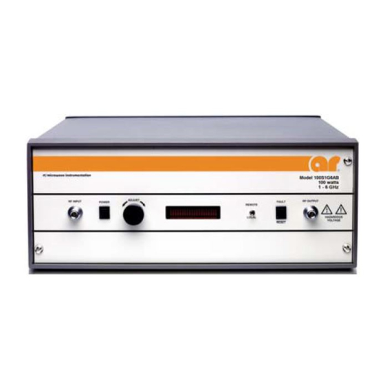
Model 100S1G6AB AMPLIFIER FRONT AND REAR PANELS Figure 2-1 shows the front panel of the Model 100S1G6AB Broadband Microwave Amplifier. Figure 2-2 shows the rear panel of the Model 100S1G6AB Broadband Microwave Amplifier. Figure 2-1. Model 100S1G6AB Front Panel Figure 2-2. Model 100S1G6AB Rear Panel LOCAL OPERATION 2.3.1... -
Page 23: Remote Communications
Model 100S1G6AB REMOTE COMMUNICATIONS This section describes remote operation of this product using the installed communications ports connected to a remote device such as a personal computer. All ports are active at all times, however only one port may be used at a time. -
Page 24: Rs-232 Communications
Model 100S1G6AB 2.4.2 RS-232 Communications The RS-232 port is a serial communications bus. All commands and queries through this port must be terminated with a <LF>. When a valid query is received, it is processed and the result is immediately transmitted back over the RS-232 interface. -
Page 25: Usb Communications
The connector type for this port is ST. This port can be used with either an AR IF7000 RS-232 to Fiber-Optic Interface or an AR IF7001 USB to Fiber-Optic Interface. Note that these devices use SMA connectors so a fiber-optic cable is needed with ST connectors on one end and SMA connectors on the other. -
Page 26: Remote Commands
Lantronix Ethernet devices. This list of found devices will include any connected AR Ethernet devices. By selecting one of the connected devices from the list, its IP address and subnet mask can be changed along with a number of other settings. -
Page 27: Power On/Off
Model 100S1G6AB 2.4.6.1 Power On/Off This command controls the power on/off state of the amplifier. Syntax: POWER:x Parameters: State(x): OFF = power off ON = power on Response Format: None (No query for this command) Example: To turn the power on, send the following command: POWER:ON<LF>... -
Page 28: Mode Select
Model 100S1G6AB 2.4.6.4 Mode Select This command sets the ALC mode of the amplifier. Syntax: MODE:x Parameters: Mode(x): MANUAL = Set to Manual mode PULSE = Set to Pulse mode* ALC<space>INT = Set to ALC Internal mode ALC<space>EXT = Set to ALC External mode*... -
Page 29: Identity
Model 100S1G6AB Example: To set the RF Gain to minimum, send the following command: LEVEL:GAIN0<LF> To set the RF Gain to 50%, send the following command: LEVEL:GAIN50<LF> To set the ALC Response Time to max, send the following command: LEVEL:RESP7<LF>... -
Page 30: Machine State
Model 100S1G6AB 2.4.6.8 Machine State This query reads the RF gain, detector gain, ALC threshold, and ALC response time of the amplifier. Syntax: MSB? Parameters: None Query only (always requires a ? character) Response Format: RF<space>GAIN=x, DT<space>GAIN=x, THRES=x, RESP=y<LF> Value(x):... -
Page 31: State
Model 100S1G6AB 2.4.6.9 State Query to find the state of the amplifier. Syntax: STATE? Parameters: None Response Format: STATE=<space>xyza<LF> Where: x, y, z, and a are each an ASCII character representing a hexadecimal character. They can be 0 to 9 or A to F. -
Page 32: Forward Power
Model 100S1G6AB Example: To read the state, send the following query. STATE?<LF> Response: STATE=<space>8301<LF> (Remote Mode, Power On, RF OFF, and Manual Mode) 2.4.6.10 Forward Power Query to get the forward power. Syntax: FPOW? Parameters: None Response Format: FPOW=x<LF> Where: x = 0 to 99999 Values are corrected and linearized. -
Page 33: Rf Gain
Model 100S1G6AB 2.4.6.12 RF Gain Query to get the RF gain. Syntax: RFG? Parameters: None Response Format: RFG=<space>x<LF> Where: x = 0000 to 0100 Example: To find out the RF gain of the amplifier, send the following query: RFG?<LF> RFG=<space>0075<LF>... -
Page 34: Operating Hours (Rf On)
Model 100S1G6AB 2.4.6.14 Operating Hours (RF On) Query to get the RF On operating hours. Syntax: Parameters: None Response Format: OH=x<LF> Where: x = 0 to 100000 Units are Hours. Values can be up to six digits in length. Leading zeros are read as spaces. -
Page 35: Ac Power-On Defaults
Model 100S1G6AB 2.4.6.16 AC Power-On Defaults Default settings that are applied at AC mains power-on can be changed by adding the following prefix to select commands. Syntax: DEFAULT: Compatible commands: Level Adjust LEVEL:GAIN LEVEL:DET (Not available on all models) LEVEL:THR... - Page 36 Model 100S1G6AB Rev A...
-
Page 37: Theory Of Operation
3. THEORY OF OPERATION INTRODUCTION The Model 100S1G6AB RF amplifier consists of a 1.0–6 GHz RF amplifier assembly. The RF amplifier assembly consists of a Pre-Amplifier (Pre-Amp), two (2) Quadrature-Coupled Amplifiers (Quad Amp) used as drivers and four (4) Quad Amps used as a final amplifier stages. -
Page 38: A2, & A3 Driver Amps
Model 100S1G6AB 3.2.2 A2, & A3 Driver Amps The Driver Amp is assembled on thin film substrates. It has two (2) GaN amplifier sections. Each section is input and output DC isolated by coupling capacitors. A 90˚ quad coupler combines the RF outputs. 50Ω... -
Page 39: A19 Regulator Board (Schematic 10031647)
Model 100S1G6AB 3.3.1 A19 Regulator Board (Schematic 10031647) The A19 regulator board filters the +24 VDC and the –24 VDC and has four (4) regulators for the RF amplifier stages. U1 is a switched 15VDC regulator. This regulator supplies voltage for the A1 pre-amplifier. - Page 40 Model 100S1G6AB Rev A...
-
Page 41: Maintenance
4. MAINTENANCE GENERAL MAINTENANCE INFORMATION The Model 100S1G6AB requires very little maintenance since it is a relatively simple instrument. It is built with etched circuit wiring and solid state devices that will ensure long, trouble free life. However, should trouble occur special care must be taken in servicing to avoid damage to the devices or the etched circuit board. -
Page 42: Troubleshooting
GaN FETs and other ESD-sensitive devices. Troubleshooting the Model 100S1G6AB in a logical manner can speed the solution to a problem. The settings of potentiometers (pots), capacitors (caps), or other variables should not be disturbed until other problems have been eliminated. -
Page 43: Power On Indication Doesn't Display On Front Panel Vacuum Fluorescent Display (Vfd) When Power Switch Is Depressed (Schematic 10038514)
Fluorescent Display (VFD) when POWER Switch is Depressed (Schematic 10038514) 1. If the Model 100S1G6AB is operating in an otherwise normal fashion, the front panel VFD or the wiring to it could be defective. 2. Check the LOCAL/REMOTE switch on the unit’s front panel; it must be set to the LOCAL position in order to operate the front panel POWER switch. -
Page 44: The Unit Cannot Be Operated Remotely
RF energy when these doors are opened. NOTE: The Model 100S1G6AB is shipped with a mating connector, which has a jumper between Pins 1 and 8, installed in the rear panel interlock connector. The unit will not operate unless the interlock circuit is closed. -
Page 45: Ps1 Fault (Schematic 10038514)
4.3.7 Low or No Power Output (DC Tests) (Schematic 10038514) All indicators on the Model 100S1G6AB are normal, the front panel vacuum fluorescent display (VFD) reads Power On, and the cooling fans (B1 and B2) are operating. 1. Check the position of the RF Gain control—is it set to maximum gain? 2. -
Page 46: Low Or No Power Output (Rf Test) (Schematic 10038514)
1. The Model 100S1G6AB’s typical gain response at 0 dBm input and -20 dBm input is shown in Figure 4- 1. The actual gain may vary considerably from that shown in Figure 4-1 but should be ≥ 47 at 0dBm input and ≥... -
Page 47: Typical Response From The A3 Quad Amplifier Input To The Main Rf Output
Model 100S1G6AB 2. With the W3 cable disconnected from the input of A3, check the response from the input of A3 to the Main RF output of the amplifier. Typical A3 Quad Amp Response is shown in Figure 4-2. Figure 4-2. Typical Gain Response from the A3 Quad Amplifier Input to the Main RF Output 3. -
Page 48: Typical 4-Way Splitter Insertion Loss And Return Loss
Model 100S1G6AB 5. A typical Four-Way Splitter insertion loss is shown in Figure 4-4. The unused ports must be terminated when checking the insertion loss. Typical combined port return loss is shown in Figure 4-4. -5.5 -6.0 -6.5 -7.0 IL J4 IL J3 -7.5... -
Page 49: Typical Quad Amp Response
Model 100S1G6AB 7. If the response of the output stages (i.e., A3 Quad Amp input to front panel RF output) is normal, check the response of the A2 Quad Amp (see Figure 4-6). Figure 4-6. Typical Quad Amp Response NOTE: The A1 Preamplifier’s response may differ considerably, particularly in flatness, from the typical response shown in Figure 4-7. - Page 50 Model 100S1G6AB Rev A...
- Page 51 These modules are not field-repairable and should never be opened outside of AR’s Microelectronics Lab. The modules in these product lines have a security label on two sides of the modules between the housing and lid/cover. If the security label is removed and or cut, the warranty of the module will be voided.
Need help?
Do you have a question about the 100S1G6AB and is the answer not in the manual?
Questions and answers