Table of Contents
Advertisement
Advertisement
Table of Contents

Related Manuals for RadioMaster T8 Pro


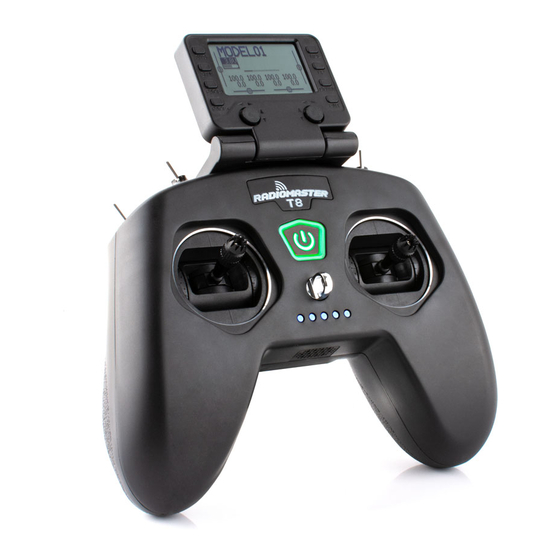
Summary of Contents for RadioMaster T8 Pro
- Page 1 T8 PRO Instruction manual Version:1.0...
-
Page 2: Table Of Contents
WWW.RADIOMASTERRC.COM TABLE OF CONTENTS 1. Overview ..................Error! Bookmark not defined. 1.1. Introduction ..............Error! Bookmark not defined. 1.2. Safety instructions ............Error! Bookmark not defined. 1.3. Manual and Firmware download ....... Error! Bookmark not defined. 1.4. Important note on firmware ........Error! Bookmark not defined. 1.5. - Page 3 4.4.1 Model settings ....................25 4.4.2. Flight Mode ......................26 4.4.3. Global Variables ....................29 4.4.4. Inputs ........................30 4.4.5. Mix control ......................33 4.4.6. Output ........................36 4.4.7. Curves ........................37 4.4.8. Logic switches ....................39 4.4.9. Special Functions ....................42 4.4.10.
-
Page 4: Overview
Do not operate the T8 Pro radio control system under the following conditions: • Under severe weather or strong wind conditions, such as rain, hail, snow, storm or harsh electromagnetic environmental conditions. -
Page 5: Manual And Firmware Download
The T8 Pro comes pre-installed with standard OpenTX firmware. To download the latest software manual, visit the RadioMaster website: https://www.radiomasterrc.com To download the latest firmware for your T8 Pro radio control, visit the OpenTX website: https://www.open-tx.org 1.4. Important note on firmware. - Page 6 1.5. Radio System Overview...
-
Page 7: Note About This Guide
1.6. Important note on `Power and charging precautions. The T8 Pro is powered by an internal 3.7V 1000mAh Lipo battery, which has a nominal voltage of 3.7V and is fully charged at 4.2V. Charging is performed via an included USB- C cable. -
Page 8: Specifications
1.9. Warranty and Repair If you experience any problems with your radio-control hardware, please keep proof of purchase and contact the retailer where you purchased T8 Pro. Also visit https://www.radiomasterrc.com/ for technical support or to find a repair agent in your... -
Page 9: Firmware Update And Opentx Information
If you decide to use OpenTX firmware, you are solely responsible for your model. Any injury or damage caused by using OpenTX firmware The authors of OpenTX and RadioMaster assume no responsibility. Use with caution. 1.12. Legal status and copyright... -
Page 10: Opentx Companion Software(Opentx Companion
2. OpenTX Companion software (OpenTX Companion) The OpenTX Companion radio control support software is used for many different tasks, such as loading OpenTX firmware to the radio, backing up model settings, editing model settings, and running the radio simulator. You can run OpenTX Companion software on multiple computer platforms. OpenTX Companion software supports common systems such as Windows, Mac OS X, and Linux. - Page 12 At this point, the OpenTX Companion software installation is complete. Please continue to follow the instructions below to continue setting the software to match the RadioMaster T8 Pro radio controller:...
-
Page 13: Use Companion Software To Update Radio Firmware
After the above settings are completed, click the firmware download button to download the firmware. Note: The RadioMaster T8 Pro radio control is pre-installed with stable and reliable OpenTX firmware when it leaves the factory. If there is no special need, please do not update the firmware unnecessarily. - Page 14 this hardware type and write the firmware correctly. The replacement method is as follows: Download the latest version of the universal driver replacement software Zadig.exe from https://zadig.akeo.ie/ A. In the Windows system, right-click Zadig-2.4.exe and select Run as administrator B. In the Zadig software, select Options-> List All Devices to view the device list C.
- Page 15 At this point, the firmware of the radio control is successfully written. Unplug the USB-C (TYPE-C) and proceed to the first boot procedures.
-
Page 16: First Boot
3. First boot Press and hold the power button to boot. Before entering the main interface, the system will check the position of the throttle stick and switch and other startup conditions. If the startup conditions are not met, there will be a corresponding error prompt. - Page 17 SD card warning: If the SD card file version used does not match the radio controller firmware version, this warning will appear. The figure requires 2.3V0026 version (the SD card content needs to be updated when upgrading the firmware). First page: Below is an example of the default first page of the system, you can customize the display elements in the page as required.
-
Page 18: Gimbal Calibration
31. Calibrating Gimbals Each T8 Pro is calibrated in the QC process however due to varying shipping conditions we suggest to calibrate your radio before first use. A. In the system settings, scroll to the HARDWARE page, select the Calibration item, and press OK to enter the settings. - Page 19 and minimum values. After all the above steps are completed, press Enter key to complete the calibration, and the system automatically returns to the previous page.
-
Page 20: Default Gimbal Mode And Channel Output Order
Mode(Gimbal mode) Because the channel input order of the built-in multi-protocol transmitting module of the RadioMaster T8 Pro radio control is AETR, in the Default channel order option, be sure to select the AETR order The Mode (gimbal mode) can be selected according to your personal... -
Page 21: Radio Menu
4. Radio menu 4.1. Main interface The default startup screen is as follows. The user can modify the content to be displayed to customize the main interface. The main interface can display the following information: Model name, TX voltage, gimbal/switch position and trim location. Scroll to show the channel position, values and channel monitor 4.1.1. -
Page 22: System Settings
4.2. System settings Long press the left SYS button to enter the system setting page. The system setting page is divided into 7 sections. TOOLS Tool page, which includes the setting function of the spectrum analyzer and some third-party equipment, such as the setting function of TBS Crossfire, Frsky specific receiver settings, and Graupner's receiver HoTT protocol settings. - Page 23 GLOBAL FUNCTIONS This page can customize various global functions. Global functions are similar to special functions in model parameters, but global functions are shared by all model, while functions in model parameters are only used by the current model. TRAINER Trainer aka Coach function page.
-
Page 24: Model Selection
VERSION On this page, you can view the radio controller hardware type, OpenTX firmware version, and the functional items included in the current firmware. 4.3. Model selection 4.3.1. Create model and model selection In the main interface, press and hold the ENT key to show the menu Select to enter the model selection page, which is used to select, create, switch, delete and copy models. -
Page 25: Model Settings(Model Setup
4.4. Model settings (Model Setup) 4.4.1 Model settings(Model setup)... - Page 26 Model Setup Detailed options: Model name:Enter your model name here. Model image:You can select a picture file as the model logo in the BMP folder of the SD card. Pictures can be viewed using the SD card manager. Timer1-3: Up to 3 fully programmable timers that can count up or down. Timer is always on Timer always on once throttle is not all the way down Timer on when throttle is not all the way down...
- Page 27 Extended trims:Fine-tuning extension, allowing fine-tuning to cover the entire gimbal range, instead of ± 25% Display trims:Modify the precision of the fine-tuning step. The accuracy can be modified according to actual requirements. Throttle:Throttle related settings Reverse:Throttle reverse : Throttle operation source (input source), because the throttle trigger Source timer is used, such as the THs function, it is usually set to the throttle channel instead of the gimbal, so that the throttle lever operation triggers the timer...
-
Page 28: Flight Mode
Internal RF:Built-in wireless RF module, built-in 4in1 multi-protocol RF module, please refer to multi-protocol RF module manual for usage : External RF module, compatible with many mainstream RF External RF modules Trainer:Trainer Mode Mode: Master/Jack Audio cable connection, coach host mode Slave/Jack Audio cable connection, student slave mode Bluetooth wireless connection, coach mode (requires external... -
Page 29: Global Variables
Mode name Define a name for the flight mode Adjust the fine-tuning value of 1-6 channels according to your Trims actual needs Fade in Slow Ease In / Ease Out Time Settings Fade Out At the bottom of the screen (below FM8) you are reminded to check the fine-tuning of each flight mode. -
Page 30: Inputs
"Global" means that global variables can be used to set pages for the entire model, but not for all models. Each model has its own set of global variables. There are 9 global variables available. 0 being the default value. Modify the value directly or press and hold the ENT key to pop up the sub-menu to change the type and parameter of the global variable. - Page 31 To set an entry, press and hold the ENT key on the current entry and a submenu will pop up Select Edit to change settings Input name: Name of the current entry. Use the scroll wheel to select a letter or number.
- Page 32 Weight: Normal range is a value between ± 100% will be zoomed to the gimbal operation. If you enter a negative value, for example -100% means reverse the output. Note that channel inversion should not use negative values on the Inputs page, and to reverse channels should be reversed on the Outputs page.
-
Page 33: Mix Control
Side: Unilateral setting with the midpoint as the boundary. No matter how this item is set, it will be set to unilateral effect by Side. x>0 All below the midpoint are fixed at 0, and normal output above the midpoint x<0 All above the midpoint is fixed at 0, and normal output below the midpoint Trim: You can choose whether the fine-tuning is effective for this entry, or you... - Page 34 By default, all lines on the same channel are added together, and the next line can choose to be superimposed or multiplied with the channel value of the previous line, and replaced completely. Please note that the currently active row of settings will be displayed in a bold font, making it easy to recognize the item currently in use at a glance.
- Page 35 name: Name setting Use the scroll wheel to select letters and numbers, and press and hold the ENT key to switch between upper and lower case. Short press the ENT key to set the next character. Source: Long press the ENT key to pop up the input source category menu. Weight: Channel travel amount, the range is -500 / + 500.
-
Page 36: Output
Modes: Select the corresponding flight mode, and the output trimming value that affects this entry can be set by the flight mode entry Switch: Select the switch to activate this item (Note: This setting is added to this item to add multiple lines of different settings to switch, if there is only one line setting, do not set the activation switch, otherwise the switch will cause this item to be completely invalid). -
Page 37: Curves
To quickly set the high/low and center points, press enter on the desired channel to open the quick-access menu Select Edit to change specific output values 4.4.7. Curves The curve can be used to modify the control response in the Inputs, Mixes, or Outputs page. - Page 38 X value represents input, such as the course of the gimbal from low to high Y value represents output, such as the process of channel output from low to high Name:Name the curve, easy to find when recalling the curve in other settings Type:Curve type Standard type, only Y point (output) can be edited, ranging from -100 to Standard...
-
Page 39: Logic Switches
Mirror:Mirror the curve vertically. Clear:Clear the current curve. 4.4.8. Logic switches(Logical Switches) The logic switch is a user-programmed virtual switch. Like the physical switch, the logic switch is also a switch, but unlike a physical switch, which can be moved by hand, the logic switch is an internal switch triggered by certain user-programmed conditions. - Page 40 is turned on when the thr gimbal is less than -90%. Triggered when the parameter v1 is approximately equal to the a~x data v2, approximately equal to the range of about 10% a>x Triggered when parameter v1 is greater than data v2 a<x Triggered when parameter v1 is less than data v2 Triggered when the absolute value of parameter v1 is greater than v2,...
- Page 41 gimbal are equal, the type of v2 at this time is not digital data, but a source a>b Triggered when parameter v1 is greater than parameter v2 a<b Triggered when parameter v1 is less than parameter v2 △ is the mathematical symbol Delta (difference value). It is triggered when the difference of the parameter v1 itself is greater △≥x than or equal to the value of data v2.
-
Page 42: Special Functions
4.4.9. Special Functions The combination of logic switches, special functions, global variables, and pass back items opens up a variety of exciting new features for the RadioMaster T8 Pro. E.g.: -Changes in battery voltage data returned by the receiver can trigger voice... - Page 43 Each setting is activated with a trigger switch. You can select physical switches, logical switches, fine-tuning buttons, and flight mode. There are two other special options, ON and Ones (which are always enabled when the machine is turned on), and One (which is performed only once when the machine is turned on) Press and hold the ENT key to enter the sub-menu for displaying sources by category.
- Page 44 anywhere Play a sound ! 1x: Play sound once, not at startup Play Sound 1x: Play sound once. 1s-60s: broadcast at intervals (seconds) Play wav file in SD card, single broadcast and loop broadcast are Play Track the same as above Voice broadcast value, can broadcast values from any source, such Play Value as real-time values such as gimbal, voltage, altitude, time, etc.
-
Page 45: Custom Scripts
4.4.10. Custom Scripts Custom script allows you to customize the functions of the radio controller. The scripting language used is Lua, which is a lightweight embeddable scripting language. You need to implement custom functions in the radio controller. There are three basic types: One-time: The script runs only once and then terminates. -
Page 46: Digital Transmission And Telemetry
4.4.11. Digital Transmission and Telemetry Each value received via digital transmission is considered a separate sensor with its own properties. Multiple identical sensor types can be connected, but the physical ID must be changed. For example, a sensor for each battery in a 2-6S lithium battery, or monitoring individual motor currents in a multi-motor model. -
Page 47: Customized Display
4.4.12. Display 4 customizable display options are available here Num: Values shown numerically, each page shows up to 8 items Bar: Values shown graphically, each page shows up to 4 bar graphs Script: Able to load third party display scripts or customized display scripts...
Need help?
Do you have a question about the T8 Pro and is the answer not in the manual?
Questions and answers