Table of Contents
Advertisement
Quick Links
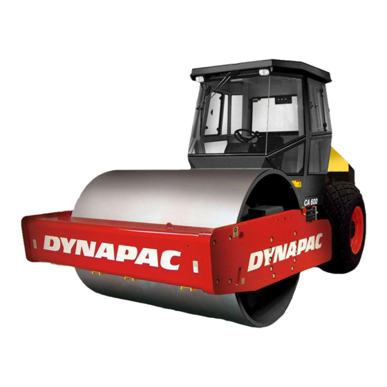
The Dynapac CA600 is available in D (smooth drum) and PD (padfoot) versions, of which the
CA600D is designed for compacting rock fill. The main range of application for the PD versions is
All types of base courses and subbase courses can be compacted deeper and the interchangeable
drums, D to PD, and vice versa, facilitate even greater variety in the range of application.
Certain accessories, such as the compaction meter, tachograph and the DCA field computer, are
Vibratory Roller
CA600
Operation
O600EN1, July 2004
Diesel engine:
CA600:
Cummins B5.9-VE-TAA
These instructions apply from:
CA600
PIN (S/N) *79X20600*
CA600
PIN (S/N) *79X2CN3700*
on cohesive material and weathered stone material.
described in separate instructions.
Reservation for changes.
Printed in Sweden.
Advertisement
Table of Contents

Related Manuals for Dynapac CA600


Summary of Contents for Dynapac CA600
- Page 1 CA600 PIN (S/N) *79X2CN3700* The Dynapac CA600 is available in D (smooth drum) and PD (padfoot) versions, of which the CA600D is designed for compacting rock fill. The main range of application for the PD versions is on cohesive material and weathered stone material.
- Page 2 CA600 PIN (S/N) *79X2CN3700* The Dynapac CA600 is available in D (smooth drum) and PD (padfoot) versions, of which the CA600D is designed for compacting rock fill. The main range of application for the PD versions is on cohesive material and weathered stone material.
-
Page 3: Table Of Contents
This manual contains instructions concerning operation Proposition 65 Warning and use of the roller. For information regarding care and maintenance, see the manual, “MAINTENANCE, CA600". Diesel engine exhaust and some of its constituents are known to the State of When starting up and driving a cold machine,... - Page 4 This manual contains instructions concerning operation Proposition 65 Warning and use of the roller. For information regarding care and maintenance, see the manual, “MAINTENANCE, CA600". Diesel engine exhaust and some of its constituents are known to the State of When starting up and driving a cold machine,...
-
Page 5: Safety Instructions (Read The Safety Manual Also)
17. Make no changes or modifications on the roller that could affect safety. Changes may only be made following written consent by Dynapac. 18. Do not use the roller until the hydraulic fluid has reached its normal work- ing temperature. - Page 6 17. Make no changes or modifications on the roller that could affect safety. Changes may only be made following written consent by Dynapac. 18. Do not use the roller until the hydraulic fluid has reached its normal work- ing temperature.
-
Page 7: Safety When Driving
Fig. 2 Tipping angle on side slopes To leave the cab in an emergency, release the hammer located on the rear right post and break the rear window. CA600 O600EN1... - Page 8 Fig. 2 Tipping angle on side slopes To leave the cab in an emergency, release the hammer located on the rear right post and break the rear window. CA600 O600EN1...
-
Page 9: Safety Decals, Location/Description
SAFETY DECALS, LOCATION/DESCRIPTION 4, 14 4, 14 CA600 O600EN1... - Page 10 SAFETY DECALS, LOCATION/DESCRIPTION 4, 14 4, 14 CA600 O600EN1...
- Page 11 Hydraulic fluid Emergency exit Warning - hot surfaces in the engine compartment. Do not touch. Lifting point Mass Lifting plate Tires filled with ballast Read the instruction manual. Securing point Battery disconnector Tire pressure Handbook compartment = Optional CA600 O600EN1...
- Page 12 Hydraulic fluid Emergency exit Warning - hot surfaces in the engine compartment. Do not touch. Lifting point Mass Lifting plate Tires filled with ballast Read the instruction manual. Securing point Battery disconnector Tire pressure Handbook compartment = Optional CA600 O600EN1...
-
Page 13: Machine And Engine Plates
Please state the PIN (serial number) of the roller when ordering spare parts. Fig. 3 Operator’s platform 1. Machine plate PIN on frame The PIN (1) of the machine is punched on the front right edge of the forward frame beam. Fig. 4 Front frame 1. PIN CA600 O600EN1... - Page 14 Please state the PIN (serial number) of the roller when ordering spare parts. Fig. 3 Operator’s platform 1. Machine plate PIN on frame The PIN (1) of the machine is punched on the front right edge of the forward frame beam. Fig. 4 Front frame 1. PIN CA600 O600EN1...
- Page 15 .508 Exh. Fuel rate at rated HP/KW 93 mm Date of MFG YYYYMMDD Firing Order 1-5-3-6-2-4 FR91089 Low Idle RPM 800 - 1100 Z Z Z Z Rated HP/kW 173/129 at 2200 Fig. 5 Engine 1. Engine plate CA600 O600EN1...
- Page 16 .508 Exh. Fuel rate at rated HP/KW 93 mm Date of MFG YYYYMMDD Firing Order 1-5-3-6-2-4 FR91089 Low Idle RPM 800 - 1100 Z Z Z Z Rated HP/kW 173/129 at 2200 Fig. 5 Engine 1. Engine plate CA600 O600EN1...
-
Page 17: Instruments And Controls
8. Brake warning lamp 19. Vibration ON/OFF 9. Warning lamp, engine oil pressure/ 20. Forward/Reverse lever Warning lamp, engine temperature 21. Test button for warning lamps 10. Warning lamp, hydraulic filter 22. Handbook compartment 11. Warning lamp, air filter = Optional CA600 O600EN1... - Page 18 8. Brake warning lamp 19. Vibration ON/OFF 9. Warning lamp, engine oil pressure/ 20. Forward/Reverse lever Warning lamp, engine temperature 21. Test button for warning lamps 10. Warning lamp, hydraulic filter 22. Handbook compartment 11. Warning lamp, air filter = Optional CA600 O600EN1...
-
Page 19: Instruments And Controls, Functional Description
Warning lamp, hydraulic This lamp lights if the hydraulic fuel is too hot. temperature Stop the roller, and allow the fluid to cool down by idling the engine. Locate and remedy the fault. CA600 O600EN1... - Page 20 Warning lamp, hydraulic This lamp lights if the hydraulic fuel is too hot. temperature Stop the roller, and allow the fluid to cool down by idling the engine. Locate and remedy the fault. CA600 O600EN1...
- Page 21 The further from neutral, the higher the speed. The lamps 10, 11, 12 are checked when the Test button for warning lamps switch is pressed. Handbook compartment Stowage space for safety manual and operator’s manuals. CA600 O600EN1...
- Page 22 The further from neutral, the higher the speed. The lamps 10, 11, 12 are checked when the Test button for warning lamps switch is pressed. Handbook compartment Stowage space for safety manual and operator’s manuals. CA600 O600EN1...
-
Page 23: Controls In The Cab
CONTROLS IN THE CAB Fig. 7b Cab roof, rear Fig. 7a Cab roof, front Fig. 7c Cab, right side Fig. 7d Cab, rear Fig. 7e Cab, left side CA600 O600EN1... - Page 24 CONTROLS IN THE CAB Fig. 7b Cab roof, rear Fig. 7a Cab roof, front Fig. 7c Cab, right side Fig. 7d Cab, rear Fig. 7e Cab, left side CA600 O600EN1...
-
Page 25: Controls In The Cab, Functional Description
Right mode, heating turned off. Air fan, switch Left mode, fan turned off. Right mode, cab (Optional) ventilation increases in three steps. Cab lighting, Press to turn on the cab lights. switch Windshield washer fluid Fill with new fluid as needed. CA600 O600EN1... - Page 26 Right mode, heating turned off. Air fan, switch Left mode, fan turned off. Right mode, cab (Optional) ventilation increases in three steps. Cab lighting, Press to turn on the cab lights. switch Windshield washer fluid Fill with new fluid as needed. CA600 O600EN1...
-
Page 27: Before Starting
• Cushioning to suit weight of operator (2). Always make sure that the seat is secure before beginning operation. Remember to use the seat belt (3). Fig. 10 Operator’s seat 1. Locking lever - length adjustment 2. Lever - weight adjustment 3. Seat belt CA600 O600EN1... - Page 28 • Cushioning to suit weight of operator (2). Always make sure that the seat is secure before beginning operation. Remember to use the seat belt (3). Fig. 10 Operator’s seat 1. Locking lever - length adjustment 2. Lever - weight adjustment 3. Seat belt CA600 O600EN1...
- Page 29 Fig. 13 Operator’s station friction is poor. 1. Seat belt 2. ROPS If the machine is fitted with a cab, make sure 3. Rubber element that the door is closed when in motion. 4. Anti-slip CA600 O600EN1...
- Page 30 Fig. 13 Operator’s station friction is poor. 1. Seat belt 2. ROPS If the machine is fitted with a cab, make sure 3. Rubber element that the door is closed when in motion. 4. Anti-slip CA600 O600EN1...
- Page 31 BEFORE STARTING Field of view Before starting, make sure that the field of view is unobstructed, both in front and behind. All cab windows must be clean and rearview mirrors properly adjusted. Fig. 14 Field of view CA600 O600EN1...
- Page 32 BEFORE STARTING Field of view Before starting, make sure that the field of view is unobstructed, both in front and behind. All cab windows must be clean and rearview mirrors properly adjusted. Fig. 14 Field of view CA600 O600EN1...
-
Page 33: Starting
7. Charging lamp Ensure that ventilation (evacuation) is 8. Brake lamp adequate if the engine is run indoors. ie, 9. Oil pressure lamp/engine danger of carbon monoxide poisoning. temperature 13. Amplitude selector 16. Revs control 20. Forward/Reverse lever CA600 O600EN1... - Page 34 7. Charging lamp Ensure that ventilation (evacuation) is 8. Brake lamp adequate if the engine is run indoors. ie, 9. Oil pressure lamp/engine danger of carbon monoxide poisoning. temperature 13. Amplitude selector 16. Revs control 20. Forward/Reverse lever CA600 O600EN1...
-
Page 35: Driving
Check and remedy any fault; see also the maintenance manual and the engine manual. If the warning lamp (11) for the air cleaner lights during operation (at full engine revs), the main filter must be cleaned or replaced; see Maintenance Manual. CA600 O600EN1... - Page 36 Check and remedy any fault; see also the maintenance manual and the engine manual. If the warning lamp (11) for the air cleaner lights during operation (at full engine revs), the main filter must be cleaned or replaced; see Maintenance Manual. CA600 O600EN1...
-
Page 37: Vibration/Driving
If the rear tires spin, set the drum drive low and the rear axle high. Set the knobs to their initial positions when grip is restored to the machine. Fig. 18 Control panel 14. Speed selector, drum 15. Speed selector, rear axle CA600 O600EN1... - Page 38 If the rear tires spin, set the drum drive low and the rear axle high. Set the knobs to their initial positions when grip is restored to the machine. Fig. 18 Control panel 14. Speed selector, drum 15. Speed selector, rear axle CA600 O600EN1...
-
Page 39: Braking
Switch off all lights and other electrical functions. Turn the starter switch (2) to mode O. Lower the instru- ment cover (on rollers without cab) and lock it. Fig. 20 Instrument panel 2. Starter switch CA600 O600EN1... - Page 40 Switch off all lights and other electrical functions. Turn the starter switch (2) to mode O. Lower the instru- ment cover (on rollers without cab) and lock it. Fig. 20 Instrument panel 2. Starter switch CA600 O600EN1...
-
Page 41: Parking
This will prevent discharging of the battery and will also make it difficult for any unauthorized person to start and drive the machine. Also lock the engine compartment cover. Fig. 22 Battery compartmen 1. Battery disconnector CA600 O600EN1... - Page 42 This will prevent discharging of the battery and will also make it difficult for any unauthorized person to start and drive the machine. Also lock the engine compartment cover. Fig. 22 Battery compartmen 1. Battery disconnector CA600 O600EN1...
-
Page 43: Instructions For Lifting
(2) fitted with a wire, to secure the locking stud (3). The locking lug (4) is located on the tractor frame. Fig. 25 Articulation in open mode 1. Locking arm 2. Locking cotter 3. Locking stud 4. Locking lug CA600 O600EN1... - Page 44 (2) fitted with a wire, to secure the locking stud (3). The locking lug (4) is located on the tractor frame. Fig. 25 Articulation in open mode 1. Locking arm 2. Locking cotter 3. Locking stud 4. Locking lug CA600 O600EN1...
-
Page 45: Towing
(1). Screw out the adjusting screws (4) to their initial position 34 mm (1.34 in) from the Fig. 27 Rear axle contact surface, and tighten the locknuts (3). 3. Locknut Tighten the four hexagonal socket screws (5). 4. Adjusting screw CA600 O600EN1... - Page 46 (1). Screw out the adjusting screws (4) to their initial position 34 mm (1.34 in) from the Fig. 27 Rear axle contact surface, and tighten the locknuts (3). 3. Locknut Tighten the four hexagonal socket screws (5). 4. Adjusting screw CA600 O600EN1...
-
Page 47: Instructions For Towing
34 mm (1.34 in) from the contact surface, and tighten the locknuts (3). Loosen the drum brake screws (5). Fig. 28 Drum brake 5. Screw Normal position Brake active Towing mode Brake disengaged Fig. 29 Drum brake 5. Screw CA600 O600EN1... - Page 48 34 mm (1.34 in) from the contact surface, and tighten the locknuts (3). Loosen the drum brake screws (5). Fig. 28 Drum brake 5. Screw Normal position Brake active Towing mode Brake disengaged Fig. 29 Drum brake 5. Screw CA600 O600EN1...
-
Page 49: Transport
Clamp down the roller with lashing strap (3) at all four corners; decals indicate the fixing points. Fig. 31 Transportation 1. Chocks Remember to restore the articulation interlock 2. Supporting blocks to its open mode before starting the roller 3. Lashing wire again. CA600 O600EN1... - Page 50 Clamp down the roller with lashing strap (3) at all four corners; decals indicate the fixing points. Fig. 31 Transportation 1. Chocks Remember to restore the articulation interlock 2. Supporting blocks to its open mode before starting the roller 3. Lashing wire again. CA600 O600EN1...
-
Page 51: Operating Instructions - Summary
Push in the reserve/parking brake knob. Stop the engine and chock the drums. 15. Lifting: – See the operation manual. 16. Towing: – See the operation manual. 17. Transport: – See the operation manual. 18. Retrieval: – See the operation manual. CA600 O600EN1... - Page 52 Push in the reserve/parking brake knob. Stop the engine and chock the drums. 15. Lifting: – See the operation manual. 16. Towing: – See the operation manual. 17. Transport: – See the operation manual. 18. Retrieval: – See the operation manual. CA600 O600EN1...
Need help?
Do you have a question about the CA600 and is the answer not in the manual?
Questions and answers