Table of Contents
Advertisement
Quick Links
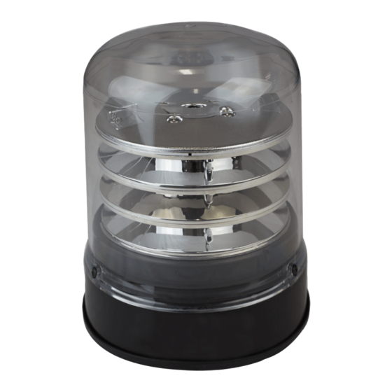
The B200 Series R65 LED Beacon features powerful LED's arranged to
produce a 360° flash pattern, with a flash rate of 125FPM for maximum
visibility. This Beacon is suitable for applications where the UK lighting
regulation Chapter 8 is a requirement. Combining the solid state,
maintenance free and long life nature of LED technology with a proven
tough housing design. This ECCO Group Europe, UK produced beacon
is designed to maximise resilience to excessive vibration and increase
the life of the product whilst offering a premium aesthetic appeal.
Failure to install or use this product according to manufacturer's recommendations may result in property
!
WARNING!
damage, serious injury, and/or death to those you are seeking to protect!
Do not install and/or operate this safety product unless you have read and understand the safety
information contained
1. Proper installation combined with operator training in the use, care, and maintenance of emergency warning devices are
essential to ensure the safety of you and those you are seeking to protect.
2. Exercise caution when working with live electrical connections.
3. This product must be properly grounded. Inadequate grounding and/or shorting of electrical connections can cause high
current arcing, which can cause personal injury and/or severe vehicle damage, including fire.
4. Proper placement and installation are vital to the performance of this warning device. Install this product so that output
performance of the system is maximized and the controls are placed within convenient reach of the operator so that s/he
can operate the system without losing eye contact with the roadway.
5. Do not install this product or route any wires in the deployment area of an air bag. Equipment mounted or located in an air
bag deployment area may reduce the effectiveness of the air bag or become a projectile that could cause serious personal
injury or death. Refer to the vehicle owner's manual for the air bag deployment area. It is the responsibility of the
user/operator to determine a suitable mounting location ensuring the safety of all passengers inside the vehicle particularly
avoiding areas of potential head impact.
6. It is the responsibility of the vehicle operator to ensure during use that all features of this product work correctly. In use, the
vehicle operator should ensure the projection of the warning signal is not blocked by vehicle components (i.e., open trunks
or compartment doors), people, vehicles or other obstructions.
7. The use of this or any other warning device does not ensure all drivers can or will observe or react to a warning signal.
Never take the right-of-way for granted. It is your responsibility to be sure you can proceed safely before entering an
intersection, driving against traffic, responding at a high rate of speed, or walking on or around traffic lanes.
8. This equipment is intended for use by authorized personnel only. The user is responsible for understanding and obeying
all laws regarding warning signal devices. Therefore, the user should check all applicable city, state, and federal laws and
regulations. The manufacturer assumes no liability for any loss resulting from the use of this warning device.
Important! This unit is a safety device, and it must be
connected to its own separate, fused power point to assure its
continued operation should any other electrical accessory fail.
Caution: The Magnet Mount is not recommended for use on
a moving vehicle, nor is it intended as a permanent mount for
the light. Long duration usage of the magnet in the presence of
moisture will cause the steel to rust.
Page 1 of 3
P/N 920-0695-00 (Rev B) 2018-02-20
INSTALLATION & OPERATING
INSTRUCTIONS
LED BEACONS - B200SERIES
Caution: When drilling into any vehicle surface, make sure the
area is free from any electrical wires, fuel lines, vehicle
upholstery, etc. that could be damaged
Advertisement
Table of Contents

Related Manuals for Ecco B200 R65


Summary of Contents for Ecco B200 R65
- Page 1 Chapter 8 is a requirement. Combining the solid state, maintenance free and long life nature of LED technology with a proven tough housing design. This ECCO Group Europe, UK produced beacon is designed to maximise resilience to excessive vibration and increase the life of the product whilst offering a premium aesthetic appeal.
- Page 2 Wire functions are as follows: Black Wire: Negative. Connect to either the battery negative terminal or a suitable chassis point. Red Wire: Power. Switch to battery positive to operate the module. Must be powered through the fuse, located as close to the battery terminal as possible.
- Page 3 Electronics Controls Company “ECCO” (Manufacturer) ECCO warrants that on the date of purchase, this product will conform to ECCO’s specifi cations for this product (which are available from ECCO upon request). This Limited Warranty extends for twelve (12) months from the date of purchase.
Need help?
Do you have a question about the B200 R65 and is the answer not in the manual?
Questions and answers