Table of Contents
Advertisement
Available languages
Available languages
!
WARNING!
Failure to install or use this product according to manufacturer's recommendations may result in property damage,
serious bodily/personal injury, and/or death to you and those you are seeking to protect!
Do not install and/or operate this safety product unless you have read and understand the safety
information.
1. Proper installation combined with operator training in the use, care, and maintenance of emergency warning de-
vices are essential to ensure the safety of you and those you are seeking to protect.
2. Exercise caution when working with live electrical connections.
3. This product must be properly grounded. Inadequate grounding and/or shorting of electrical connections can cause
high current arcing, which can cause personal injury and/or severe vehicle damage, including fire.
4. Proper placement and installation are vital to the performance of this warning device. Install this product so that
output performance of the system is maximized and the controls are placed within convenient reach of the operator
so that s/he can operate the system without losing eye contact with the roadway.
5. Do not install this product or route any wires in the deployment area of an air bag. Equipment mounted or located in
an air bag deployment area may reduce the effectiveness of the air bag or become a projectile that could cause se-
rious personal injury or death. Refer to the vehicle owner's manual for the air bag deployment area. It is the respon-
sibility of the user/operator to determine a suitable mounting location ensuring the safety of all passengers inside
the vehicle particularly avoiding areas of potential head impact.
6. It is the responsibility of the vehicle operator to ensure during use that all features of this product work correctly. In
use, the vehicle operator should ensure the projection of the warning signal is not blocked by vehicle components
(i.e., open trunks or compartment doors), people, vehicles or other obstructions.
7. The use of this or any other warning device does not ensure all drivers can or will observe or react to a warning sig-
nal. Never take the right-of-way for granted. It is your responsibility to be sure you can proceed safely before enter-
ing an intersection, driving against traffic, responding at a high rate of speed, or walking on or around traffic lanes.
8. This equipment is intended for use by authorized personnel only. The user is responsible for understanding and
obeying all laws regarding warning signal devices. Therefore, the user should check all applicable city, state, and
federal laws and regulations. The manufacturer assumes no liability for any loss resulting from the use of this warn-
ing device.
Specifications:
Voltage: Models EB7810-EB7816: 12 or 24* VDC
Model Number
Size
EB7810
6" dia. x 8.3 height
EB7813
6" dia. x 5.7 height
EB7813-MG
6.6" dia. x 6 height
EB7816
6" dia. x 7.3 height
Current Draw:
1.36 Amps @ 12 VDC, 0.64 Amps @ 24
VDC
Flash Rate:
180 per minute
*See wiring instructions below for 24 VDC systems
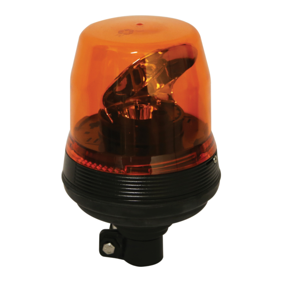
Installation & Mounting:
Carefully remove the rotating beacon and examine the unit
for transit damage, broken lamps, etc. If damage is found,
contact the transit company or ECCO. Do not use broken or
damaged parts.
Installation Instructions
EB7800 Series Rotating Beacon
!
Weight
1.70 lbs
When drilling into any vehicle surface, make sure that the area is free
1.20 lbs
from any electrical wires, fuel lines, vehicle upholstery,etc. that could
2.05 lbs
be damaged.
1.55 lbs
CAUTION:
Page 1 of 4
Advertisement
Table of Contents

Related Manuals for Ecco EB7800 Series


Summary of Contents for Ecco EB7800 Series
- Page 1 *See wiring instructions below for 24 VDC systems Installation & Mounting: Carefully remove the rotating beacon and examine the unit for transit damage, broken lamps, etc. If damage is found, contact the transit company or ECCO. Do not use broken or damaged parts. Page 1 of 4...
- Page 2 Quick Connect (DIN/Pole Mount) Rotating Beacon: EB7810 Three Bolt Mount Rotating Beacon: EB7813 (Refer to FIGURE 1) These beacons are designed for pipe mounting on a ¾” pipe, and connected to power via a standard DIN connector (See FIGURE 2). Select the mounting location for the beacon on a flat, smooth To mount, simply plug in the DIN connector, place on the pipe, and surface.
-
Page 3: Wiring Instructions
Wiring Instructions: Replacement Parts and Accessories: Important! Disable power before wiring the beacon. Description Part Number The wiring is as shown in FIGURE 4. All wiring should be a mini- Replacement Lens, Amber R5810LA mum of 18AWG. The positive line must have a 5 amp fuse, as shown. -
Page 4: Customer Service
Manufacturer Limited Warranty and Limitation of Liability: Manufacturer warrants that on the date of purchase this product will conform to Manufacturer’s specifications for this product (which are available from the Manufacturer upon request), and Manufacturer further warrants that this product is free from defects in materials and workmanship. -
Page 5: Especificaciones
Retire cuidadosamente la baliza giratoria y examine la unidad para ver si se ha dañado en el tránsito, si hay luces rotas, etc. Si hay daños, contacte a la compañía de transporte o a ECCO. No use partes rotas o dañadas. - Page 6 Conexión rápida de la baliza giratoria Baliza giratoria con ensamblaje de tres pernos: EB7813 (Consulte la FIGURA 1) (ensamblaje en riel/tubo): EB7810 Estas balizas han sido diseñadas para ser ensambladas en tubo, en un tubo de ¾” y conectadas a una fuente de corriente a través Seleccione la ubicación del ensamblaje para la baliza en una de un conector DIN estándar (Ver FIGURA 2).
-
Page 7: Instrucciones De Cableado
Instrucciones de cableado: Repuestos y accesorios: ¡Importante! Deshabilite la energía antes de cablear la baliza. Descripción Número de parte El cableado se muestra en la FIGURA 4. Todo el cableado debe Lente de reemplazo, ámbar R5810LA ser de un mínimo de 18 AWG (0.83 mm²). La línea positiva debe tener un fusible de 5 amp, como se muestra. - Page 8 Limitación de responsabilidad y garantía limitada del fabricante: El fabricante garantiza que al momento de la compra, este producto cumple con las especificaciones del fabricante para el mismo (disponibles a pedido). El fabricante garantiza además que el presente producto está libre de defectos en sus materiales y en su fabricación.
- Page 9 Enlevez soigneusement le gyrophare et examinez l'unité pour déceler les dommages survenus en cours de transport, des lampes cassées, etc. Si des dommages sont constatés, contac- tez la compagnie de transport ou ECCO. Ne pas utiliser des pièces endommagées ou cassées. Page 1 sur 4...
- Page 10 Gyrophare à trois boulons de montage : Gyrophare à connexion rapide (DIN / montage sur poteau) : EB7813 (voir la FIGURE 1) EB7810 Ces gyrophares sont conçus pour être montés sur un tuyau de ¾ po et reliés à l'alimentation via un connecteur DIN standard (voir FIGURE 2). Sélectionnez l'emplacement de montage du gyrophare sur une Pour le montage, il suffit de brancher le connecteur DIN, de le surface plane et lisse.
-
Page 11: Instructions De Câblage
Instructions de câblage : Pièces de rechange et accessoires : Important ! Désactiver l'alimentation avant de câbler le gyrophare. Description Numéro de référence Le câblage se fait comme indiqué sur la FIGURE 4. Tout le Ampoule de rechange, ambre R5810LA câblage doit être un minimum de 18 AWG (0,83 mm²). - Page 12 Garantie limitée et limitation de responsabilité du fabricant : Le fabricant garantit qu’à la date d’achat ce produit sera conforme aux caractéristiques techniques définies par ses soins (disponibles sur demande) et qu’il est exempt de vices de fabrication et de main-d’œuvre. La présente garantie limitée est valable trente-six (36) mois à compter de la date d’achat. D’autres garanties peuvent s’appliquer.
Need help?
Do you have a question about the EB7800 Series and is the answer not in the manual?
Questions and answers