Table of Contents
Advertisement
Available languages
Available languages
Quick Links
!
WARNING!
Failure to install or use this product according to manufacturer's recommendations may result in property damage, serious injury, and/or death to
those you are seeking to protect!
Do not install and/or operate this safety product unless you have read and understand the safety information
contained
1.
Proper installation combined with operator training in the use, care, and maintenance of emergency warning devices are essential to ensure
the safety of you and those you are seeking to protect.
2.
Exercise caution when working with live electrical connections.
3.
This product must be properly grounded. Inadequate grounding and/or shorting of electrical connections can cause high current arcing,
which can cause personal injury and/or severe vehicle damage, including fire.
4.
Proper placement and installation are vital to the performance of this warning device. Install this product so that output performance of the
system is maximized and the controls are placed within convenient reach of the operator so that s/he can operate the system without losing
eye contact with the roadway.
5.
Do not install this product or route any wires in the deployment area of an air bag. Equipment mounted or located in an air bag deployment
area may reduce the effectiveness of the air bag or become a projectile that could cause serious personal injury or death. Refer to the
vehicle owner's manual for the air bag deployment area. It is the responsibility of the user/operator to determine a suitable mounting location
ensuring the safety of all passengers inside the vehicle particularly avoiding areas of potential head impact.
6.
It is the responsibility of the vehicle operator to ensure during use that all features of this product work correctly. In use, the vehicle operator
should ensure the projection of the warning signal is not blocked by vehicle components (i.e., open trunks or compartment doors), people,
vehicles or other obstructions.
7.
The use of this or any other warning device does not ensure all drivers can or will observe or react to a warning signal. Never take the right-
of-way for granted. It is your responsibility to be sure you can proceed safely before entering an intersection, driving against traffic, respond-
ing at a high rate of speed, or walking on or around traffic lanes.
8.
This equipment is intended for use by authorized personnel only. The user is responsible for understanding and obeying all laws regarding
warning signal devices. Therefore, the user should check all applicable city, state, and federal laws and regulations. The manufacturer as-
sumes no liability for any loss resulting from the use of this warning device.
Specifications:
Size:
Permanent Mount
Pipe Mount
Weight:
Permanent Mount
Pipe Mount
Voltage:
Current Draw @ 12.8 VDC:
EB7260A, EB7260CA
EB7265A, EB7265CX
EB7265CXX
Flash Rate:
Temp. Range:
Installation & Mounting:
Carefully remove the beacon and place it on a flat surface. Examine the unit
for transit damage, broken lenses, etc. If damage is found, contact the transit
company or distributor. Do not use damaged or broken parts.
Permanent Mounting:
Caution: When drilling into any vehicle surface, make sure the area is free
from any electrical wires, fuel lines, vehicle upholstery, etc. that could be
damaged
Position the beacon in the desired mounting location. Using the base flange as
a template, mark the mounting hole locations. Drill three 13/64" mounting holes.
Drill a hole for power wire routing as desired. The use of a grommet is recom-
mended for wires passing through compartment walls. Secure the beacon in
place using customer supplied #10 hardware.
Pipe Mounting:
Remove the surface mount flange and four screws from the beacon's base.
Route the wires through the 1/2" NPT thread pipe and thread the beacon on until
secured.
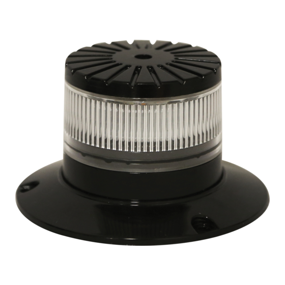
Installation and Operation Instructions
EB7260 & EB7265 Series Multi Mount
W: 5.0" Dia. x 3.0" H
W: 3.2" Dia. x 2.5" H
0.94 lb.
0.84 lb.
12-24 VDC Systems
1.0 A. Max
1.7 A. Max
1.7 A. Max
See Flash Pattern Chart
-22°F to 122°
-30°C to 50°C
LED Beacons
Wiring Instructions:
Important! This unit is a safety device, and it must be connected to its own
separate, fused power point to assure its continued operation should any
other electrical accessory fail.
Wiring for single and dual color beacons are as shown in FIGURE 1. All wiring
should be a minimum of 20 AWG. The positive line must have a 3 amp fuse,
as shown. A switch may be used to control the on/off function. Route the
ground wire directly back to negative battery terminal. Pack dielectric grease,
such as Dow Corning 4, around each electric connection exposed to moisture
or the ambient environment.
Important!
Disable power before wiring the beacon.
SINGLE COLOR
EB7260 & EB7265
FUSE (3A)
(USER SUPPLIED)
(+)
(-)
DUAL COLOR
EB7265
FUSE (3A)
(USER SUPPLIED)
(+)
(-)
RED
SWITCH
(USER SUPPLIED)
BLACK
YELLOW - SYNC
BLUE - FLASH PATTERN SELECT
MOMENTARY TO GROUND (-)
ISOLATE WHEN NOT IN USE
RED
SWITCH
(USER SUPPLIED)
YELLOW - SYNC
WHITE
SWITCH
(USER SUPPLIED)
BLACK
BLUE - FLASH PATTERN SELECT
MOMENTARY TO GROUND (-)
ISOLATE WHEN NOT IN USE
FIGURE 1
Page 1 of 8
Advertisement
Table of Contents

Related Manuals for Ecco EB7260 Series


Summary of Contents for Ecco EB7260 Series
- Page 1 Installation and Operation Instructions EB7260 & EB7265 Series Multi Mount LED Beacons WARNING! Failure to install or use this product according to manufacturer’s recommendations may result in property damage, serious injury, and/or death to those you are seeking to protect! Do not install and/or operate this safety product unless you have read and understand the safety information contained Proper installation combined with operator training in the use, care, and maintenance of emergency warning devices are essential to ensure...
- Page 2 Synchronization: Syncing capabilities are available with all compatible ECCO products via the yellow wire with the flash patterns indicated in the charts below: 1. Determine the desired style of flash pattern for each unit and set each unit individually (without the yellow wires connected together) to avoid confusion. It is also strongly recommended that the same style of flash pattern be used on all units to produce the most effective warning pattern.
- Page 3 Page 3 of 8...
- Page 4 Page 4 of 8...
- Page 5 Page 5 of 8...
- Page 6 Page 6 of 8...
- Page 7 Page 7 of 8...
-
Page 8: Customer Service
Manufacturer Limited Warranty and Limitation of Liability: Manufacturer warrants that on the date of purchase, this product will conform to Manufacturer’s specifications for this product (which are available from the Manufacturer upon request). This Limited Warranty extends for thirty-six (36) months from the date of purchase. DAMAGE TO PARTS OR PRODUCTS RESULTING FROM TAMPERING, ACCIDENT, ABUSE, MISUSE, NEGLIGENCE, UNAPPROVED MODIFICATIONS, FIRE OR OTHER HAZARD;... -
Page 9: Especificaciones
Instrucciones de instalacion y operacion de las balizas LED serie EB7260 y EB7265 de ensamblaje multiple ¡ADVERTENCIA! En caso de no instalar ni utilizar este producto conforme a las sugerencias del fabricante se podrían ocasionar daños a la propiedad, lesiones graves personales o el deceso del usuario y de las personas que se busca proteger. - Page 10 Sincronización: Las capacidades de sincronización están disponibles con todos los productos ECCO compatibles mediante el cable amarillo; los patrones de parpadeo se indican en las siguientes tablas: 1. Determine el estilo deseado del patrón para cada unidad y configure cada unidad individualmente (sin los cables amarillos conectados) para evitar confusión. Además, es muy recomendable utilizar el mismo estilo de patrón de parpadeo en todas las unidades a fin de producir el patrón de advertencia más eficaz.
-
Page 11: Spécifications
Instructions d’installations et d’utilisation pour les phares DEL séries EB7260 et EB7625 montage multiple AVERTISSEMENT! Le non-respect des recommandations d’installation ou d’utilisation du fabricant peut entraîner des matériels, de graves blessures et/ou votre mort et celle de ceux que vous cherchez à protéger! N’installez et/ou n’utilisez ce produit de sécurité... - Page 12 Synchronisation : Les capacités de synchronisation sont disponibles avec tous les produits ECCO compatibles via le fil jaune avec les motifs de clignotement indiqués dans les tableaux ci-dessous : 1. Déterminez le motif de clignotement souhaité pour chaque unité et réglez chaque unité individuellement (sans les fils jaunes connectés ensemble) pour éviter toute confusion.
Need help?
Do you have a question about the EB7260 Series and is the answer not in the manual?
Questions and answers