Advertisement
!
Failure to install or use this product according to manufacturer's recommendations may result in property
WARNING!
damage, serious injury, and/or death to those you are seeking to protect!
Do not install and/or operate this safety product unless you have read and understand the safety information
contained
1.
Proper installation combined with operator training in the use, care, and maintenance of emergency warning devices are essential to
ensure the safety of you and those you are seeking to protect.
2.
Exercise caution when working with live electrical connections.
3.
This product must be properly grounded. Inadequate grounding and/or shorting of electrical connections can cause high current
arcing, which can cause personal injury and/or severe vehicle damage, including fire.
4.
Proper placement and installation are vital to the performance of this warning device. Install this product so that output performance
of the system is maximized and the controls are placed within convenient reach of the operator so that s/he can operate the system
without losing eye contact with the roadway.
5.
Do not install this product or route any wires in the deployment area of an air bag. Equipment mounted or located in an air bag
deployment area may reduce the effectiveness of the air bag or become a projectile that could cause serious personal injury or death.
Refer to the vehicle owner's manual for the air bag deployment area. It is the responsibility of the user/operator to determine a suit-
able mounting location ensuring the safety of all passengers inside the vehicle particularly avoiding areas of potential head impact.
6.
It is the responsibility of the vehicle operator to ensure during use that all features of this product work correctly. In use, the vehicle
operator should ensure the projection of the warning signal is not blocked by vehicle components (i.e., open trunks or compartment
doors), people, vehicles or other obstructions.
7.
The use of this or any other warning device does not ensure all drivers can or will observe or react to a warning signal. Never take
the right-of-way for granted. It is your responsibility to be sure you can proceed safely before entering an intersection, driving against
traffic, responding at a high rate of speed, or walking on or around traffic lanes.
8.
This equipment is intended for use by authorized personnel only. The user is responsible for understanding and obeying all laws
regarding warning signal devices. Therefore, the user should check all applicable city, state, and federal laws and regulations. The
manufacturer assumes no liability for any loss resulting from the use of this warning device.
Specifications:
Size:
W: 167mm Dia. x 85mm H
Weight:
0.85kg
Voltage:
10-32V DC Systems
Current Draw @ 13.8VDC:
4.4A Peak, 1.6A Max
Current Draw @ 27.6VDC:
2.2A Peak, 0.8A Max
Flash Rate:
See Flash Pattern Chart
Temp. Range:
-40°C to +60°C
Reverse polarity protection.
Ambient light sensor (refer flash pattern table).
Certifications:
Ingress Protection: IP69K
EMC: ECE R10, CISPR-25, ACMA RCM
SAE J845 Class 1 - refer flash pattern table.
Installation & Mounting:
Carefully remove the beacon and place it on a flat surface. Examine the
unit for transit damage, broken lenses, etc. If damage is found, contact the
transit company or distributor. Do not use damaged or broken parts.
Permanent Mounting:
Caution: When drilling into any vehicle surface, make sure the area
is free from any electrical wires, fuel lines, vehicle upholstery, etc. that
could be damaged
Position the beacon in the desired mounting location. Using the base flange
as a template, mark the mounting hole locations. Drill three 5.2mm mounting
holes. Drill a hole for power wire routing as desired. The use of a grommet
or silicone is required for wires passing through compartment walls, or
where sealing is required. Secure the beacon in place using the included
#10 hardware.
Page 1 of 4
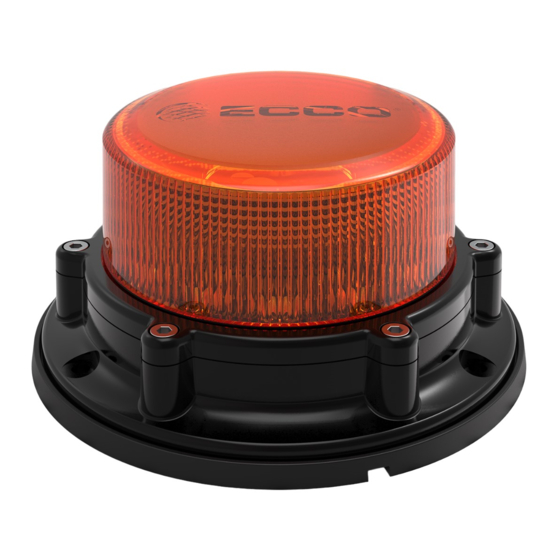
Installation and Operating Instructions
EB8160 - Heavy duty beacon
Wiring Instructions:
Important! This unit is a safety device, and it must be connected to
its own separate, fused power point to assure its continued operation
should any other electrical accessory fail.
Wiring for single colour beacons is as shown in FIGURE 1. All wiring should
be a minimum of 2mm². The positive line must have a 10A automotive
fuse, as shown. A switch may be used to control the on/off function. Route
the ground wire directly back to negative battery terminal. Pack dielectric
grease, such as Dow Corning 4, around each electric connection exposed
to moisture or the ambient environment.
Important!
Disable power before wiring the beacon.
Advertisement
Table of Contents

Related Manuals for Ecco EB8160


Summary of Contents for Ecco EB8160
- Page 1 Installation and Operating Instructions EB8160 - Heavy duty beacon Failure to install or use this product according to manufacturer’s recommendations may result in property WARNING! damage, serious injury, and/or death to those you are seeking to protect! Do not install and/or operate this safety product unless you have read and understand the safety information...
- Page 2 Synchronisation: Syncing capabilities are available with all compatible ECCO products via the yellow wire with the flash patterns indicated in the charts below: 1. Determine the desired style of flash pattern for each unit and set each unit individually (without the yellow wires connected together) to avoid confusion. It is also strongly recommended that the same style of flash pattern be used on all units to produce the most effective warning pattern.
- Page 3 THIS PAGE INTENTIONALLY LEFT BLANK Page 3 of 4...
- Page 4 This Limited Warranty defines specific legal rights. You may have other legal rights which vary from jurisdiction to jurisdiction. Some jurisdictions do not allow the exclusion or limitation of incidental or consequential damages. ECCO Safety Group Asia Pacific 439 Boundary Rd,Truganina...
Need help?
Do you have a question about the EB8160 and is the answer not in the manual?
Questions and answers