
Related Manuals for Seepex BCSB Series


Summary of Contents for Seepex BCSB Series
- Page 1 Not Binding Operating and Assembly Instruction Progressive Cavity Pump This operating and assembly instruction is only for general information. Type Issue .0 .2017...
- Page 3 Index Index Index Index 1 1 1 1 Safety Safety ..........................................................................................1 1 1 1 Safety Safety..............................General notes Safety and warning notes 1.2.1 Warning notes 1.2.2 Danger symbols 1.2.3 Information symbols Dangers that can be caused by the machine Qualification of the personnel Authorised people 1.5.1...
- Page 4 Index Index Index Index 5 5 5 5 Assembly / Installation Assembly / Installation ................................................Assembly / Installation Assembly / Installation................................................11 Mounting tools / lifting gear Space requirement 5.2.1 Dimension for stator replacement Assembly of the complete mounted pump Power supply of the pump Pipelines 5.5.1...
- Page 5 Index Index Index Index Rotating unit – individual parts ....................29 9.2.1 Dismantling 9.2.2 Rotating unit (RTE) - prepare individual parts for reassembly 9.2.3 Rotating unit (RTE) - individual parts - reassembly Holding band - assembly......................33 9.3.1 Prepare the holding band 9.3.2 Check the holding band 9.3.3...
- Page 7 Safety General notes Always keep the operating and maintenance instructions close by the machine. If problems cannot be solved with reference to the operating and maintenance instructions, please contact the manufacturer. Observe the following points in addition to these operating and maintenance instructions: •...
- Page 8 • List item Dangers that can be caused by the machine seepex machines are built in accordance with the state of the art. Nevertheless, there is a residual risk, because the machine works with: • Mechanical movements that pose a danger •...
- Page 9 Avoid/limit risks by the use of collective technical protective equipment or by organisational measures at work. Safety and protective devices Prior to start-up, bolt seepex machines onto a concrete foundation so as to ensure stability. Starting and stopping devices must be clearly recognisable. Take appropriate measures to avoid defects.
- Page 10 Safety Designated use • Only use seepex machines if they are in perfect condition and in compliance with the oper- ating and maintenance instructions. • Do not start up the machine unless the system in which the machine is installed is in accor- dance with the provisions of the applicable guidelines and statutory regulations.
-
Page 11: Description Of The Pump
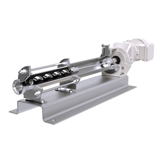
Description of the pump General description seepex pumps are members of the group of rotating displacement pumps. • Characteristic features – Special configuration/arrangement of the rotor and stator pumping elements. – Motion sequence Mode of action and pumping principle of the seepex pump •... -
Page 13: Technical Data
Technical data Data sheet Characteristic Curves Declaration • Data sheet, characteristic curves and declarations are commission specific documents and not part of this not binding operating and assembly instruction. Ausgabe Dokument Blatt A / 29.06.2017 1 (1) OM.TED.XXe issue document sheet... - Page 15 Comply with the symbols and notices on the packaging. Remove the screwed connection between the machine and packaging. Remove the machine with a lifting machine/industrial truck. Temporary storage/Corrosion protection • All seepex machines have corrosion protection applied as standard prior to transport. Ausgabe Dokument Blatt D / 27.08.2012 OM.TRA.01e...
- Page 16 Property damage can occur due to corrosion. Temporary storage must be in a dry, enclosed, frost-free room in order to provide protec- tion against ambient influences. Contact seepex regarding the necessary corrosion protection for temporary storage. Disposal NOTICE Environmental protection Material damage can occur.
-
Page 17: Assembly & Installation
Assembly / Installation Mounting tools / lifting gear CAUTION Pump falling over. Slight injury or damage to property can occur. Adhere to the lifting tool’s starting point. Pay attention to the dimensions, weight and centre of gravity of the pump. Use suitable mounting tools/lifting gear. - Page 18 Assembly / Installation Power supply of the seepex pump DANGER Supply voltage and power frequency. Death or serious injury will result. Heed type plate on the pump. Pay attention to manufacturer’s directions (→ chapter 13.). Pay attention to safety regulations.
-
Page 19: Commissioning / De-Commissioning
Date of installation: Assembly check carried out on: Please enter operational data: Conveying liquid: Temperature: Fuse level/motor protection or power consumption Frequency control If yes: Supplied by seepex Supplied by customer Frequency: Speed: Power consumption: ________________________________ _______________________________________ Place, date Signature / company stamp... - Page 21 Commissioning / De-commissioning Measures before commissioning Note the technical data (chapter 3.). 6.2.1 Checking pipelines Check flange screwed connections (SCH). Check threaded connections (G). NOTICE Ensure the liquid can flow through without obstruction. Malfunction and/or irreparable damage to the pump. ...
- Page 22 Complete failure of the pump. Make sure that the suction-side conveying capacity does not cavitate. If this cannot be guaranteed on the machine side, assemble a seepex dry running protection (TSE). 6.3.2 Pressure in the suction and pressure connection CAUTION High pressure.
- Page 23 Commissioning / De-commissioning De-commissioning Protect the pump and additional devices against the following: • Frost • Deposit of solids • Sedimentation from the liquid • Corrosion of parts that come into contact with the medium 6.4.1 Switching off the pump DANGER Dangerous voltage.
- Page 24 6.4.4 Preservation/storage of the pump NOTICE Damage to property due to lack of corrosion protection. Property damage can occur due to corrosion. Contact seepex to discuss suitable preservation measures. – State the commission number of the pump. Ausgabe Dokument Blatt C / 02.11.2012...
-
Page 25: Maintenance
Acquisition of a set of wearing parts and a set of gaskets. Lubrication Denomination Lubricant Lubricant change in Fill volume operating hours Pin joint seepex special grease 10000 h Pin joint seepex special grease 10000 h Drive Refer to manufacturer's documentation (chapter 13._) Rotor/stator... - Page 26 Maintenance 7.2.1 Joint grease NOTICE Other grease types. Malfunction and/or irreparable damage to the joints or the pump. Exclusively use seepex special grease. Inspection Component Interval Action Joints Every 10,000 operating hours Renew joint grease Stator Every week Visual check for leaks...
- Page 27 The pumps can be cleaned and disinfected in a circular or flow process without having to be dismantled. 7.4.2 Observed guidelines • seepex pumps of the CS range are certified in accordance with 3-A Sanitary Standards (USA) (model designations: BCSO, BTCS, MDC, MDTC) and designed according to the EHEDG guideline.
- Page 28 Maintenance 7.4.4 Designs 7.4.4.1 BCSO, MDC ranges • Rotating unit (RTE) with open joints. • Certified in accordance with 3-A Sanitary Standards and designed according to EHEDG guidelines. • Conveying capacities: BCSO 30 l/h - 130 m³/h; MDC range 0.5 l/h - 500 l/h. •...
- Page 29 Maintenance 7.4.6 Cleaning processes (CIP/SIP) Suction side Pressure side Valve closed (observe flow direction) Valve opened (observe flow direction) Centrifugal pump (CIP pump); customer side Bypass line; customer side Pipeline (suction side); customer side Pipeline (pressure side); customer side General •...
- Page 30 1% at 50- adherent contamination Post-flushing Fresh water Flushing out residual cleaning agent NOTICE Application of other cleaning agents Damage to property can occur. Consult with seepex Ausgabe Dokument Blatt A / 19.07.2011 OM.RCS.01e 4 (5) issue document...
- Page 31 Maintenance 7.4.6.3 Cleaning recommendations for SIP • Clean the pump so that it conforms to the required hygiene regulations. • Perform customer installation according to the figure in chapter 7.4.6. • Install the pump so that it can be cleaned residue-free at the application location. •...
- Page 33 Malfunctions, causes, rectification Refer to technical data (chapter 3.) for application range of the pump. Malfunction Causes Rectification X Static friction between sta- Apply lubricant (liquid soap) tor/rotor too great. between stator and rotor. Incorrect direction of rota- Check direction of rotation tion.
- Page 34 Stator/rotor worn. Dismantle pump and renew defective parts. Joint parts worn. Renew joint parts, use seepex pin joint grease. Suction pipe blocked. Clean the suction pipe. Temperature of pumping Check temperature, use liquid too high. an undersize rotor.
-
Page 35: Dismantling / Reassembly
Dismantling / Reassembly Pump Dismantling / Reassembly Range: BCSB Size: 025-12 to 1-6L, 1-6 to 75-6LT 9.1.1 Prepare the pump for dismantling DANGER Dangerous voltage. Death or serious injury can occur. Note safety regulations. Disconnect pump from all sources of energy. ... - Page 36 Dismantling / Reassembly 9.1.2.2 Stator (601) - dismantling Lift/slide splash ring (310). Push out plug-in shaft pin (309) horizontal- Turn plug-in shaft pin (309) upwards. Tool (W2/chain pipe wrench) Add lubricant (liquid soap) to the opening on pressure branch side between the rotor (600) and the stator (601).
- Page 37 Dismantling / Reassembly Without flush connection Tool (W10/ dismantling of the plug-in shaft) Pull rotating unit (RTE) with shaft seal (SEA) off from the output shaft of the drive (ANT). Dismantle shaft seal (SEA). – Note dismantling shaft seal (chapter 9._).
- Page 38 Dismantling / Reassembly 9.1.3.2 Rotor (600), coupling rod (400), plug-in shaft (307) - reassembly Joint (G) reassembly – Note rotating unit - individual parts (chapter 9._). 9.1.3.3 Rotating unit (RTE) - reassembly Assemble shaft seal casing (SEA). – Note reassembly shaft seal (chapter 9._).
- Page 39 Dismantling / Reassembly 9.1.3.5 Stator (601) - reassembly Insert plug-in shaft pin (309). Twist plug-in shaft pin (309) upwards. Tool (W2/chain pipe wrench) Add lubricant (GM) to the opening on the pressure branch side between the rotor (600) and stator (601).
- Page 41 Dismantling / Reassembly Rotating unit individual parts 9.2.1 Dismantling 9.2.1.1 Holding band (406, 407) - dismantling CAUTION Danger of injury. Parts might be thrown out. Wear safety glasses. Detach holding band loop (SCL). – Use suitable tool (WH). ...
- Page 42 Dismantling / Reassembly Bend (A) the coupling rod (400). Knock guide bushing (403) out with tool (W5). Remove coupling rod (400). 9.2.2 Rotating unit (RTE) - prepare individual parts for reassembly 9.2.2.1 Rotor (600) Remove any damage. ...
- Page 43 Slide the universal joint sleeve (405) and holding bands (406, 407) onto coupling rod (400). Fit the diameter and width of the holding band of the universal joint sleeve. Fill the joint head with seepex joint grease. Rotor (600) ...
- Page 44 Dismantling / Reassembly Plug-in shaft (307) Insert coupling rod pins (402). Slide on retaining sleeve (401). Connect plug-in shaft/coupling rod. Tool (W5/drift) Slide in the coupling rod pins (402). Knock the guide bushings (403) in. –...
- Page 45 Dismantling / Reassembly 9.2.3.3 Universal joint sleeve (405) - reassembly Moisten the surface of coupling rod (400) / inner surface of universal joint sleeve (405) with joint grease (maintenance chapter 7.). Slide on universal joint sleeve (405). ...
- Page 47 Dismantling / Reassembly Holding band - assembly 9.3.1 Prepare the holding band Only use prefabricated double-band holding bands may. 9.3.2 Check the holding band • Bent-over holding band (HBD) is in con- tact with holding band loop (SCL) to avoid damaging universal joint sleeve.
- Page 48 Dismantling / Reassembly 9.3.5 Cant up the holding band Swivel mounting tool (W3) approx. 60° up- wards. Loosen crank (KU) by a half turn. Swivel cutting lever (SH) forward until the pressure piece is lying behind the holding band loop (SCL).
- Page 49 Wear suitable protective clothing. Dispose of leakage appropriately. Note applicable regulations when handling hazardous substances. 9.4.2 Operating conditions and material combination • Adjust to the relevant application Design variants you will find at http://www.seepex.com/en/service/downloads/. – Dokument Ausgabe Blatt A / 29.06.2017 OM.SEA.XXe...
-
Page 51: Spare Parts
Spare parts 10.1 Spare parts list Ausgabe Dokument Blatt B / 29.03.2011 OM.SZG.02e 1 (1) issue document sheet... - Page 53 Commission: Type: Contact: ............Tel.: .............._________________________ _______________________ Fax: ............... E-mail: ............Customer service: Germany Tel +492041.996-231 Delivery address: seepex GmbH Fax +492041.996-431 ............... Postfach 10 15 64 Rest of Europe Tel +492041.996-224 ............... Fax +492041.996-424 D-46215 Bottrop ............... service@seepex.com Outside Europe Tel +492041.996-120...
- Page 54 Spare parts Version for copying Quantity Component Material Comment Set of gaskets Splash ring Mechanical seal according to data sheet (chapter 3.1) Casing gasket Sealing ring O-ring Sealing ring Plug-in shaft & shaft seal Plug-in shaft Plug-in shaft pin Splash ring Mechanical seal according to data sheet (chapter 3.1) Coupling rod &...
-
Page 55: Special Tools
Tel.: ..............__________________________ Fax: ............... E-mail: ............Customer service: Germany Tel +492041.996-231 Delivery address: Fax +492041.996-431 ............... seepex GmbH Postfach 10 15 64 Rest of Europe Tel +492041.996-224 ............... D-46215 Bottrop Fax +492041.996-424 ............... service@seepex.com Outside Europe Tel +492041.996-120 ............... -
Page 57: Associated Documents
Associated documents 12.1 Accessories/Technical information • Accessories and technical information are commission specific documents not part of this not binding operating and assembly instruction. Ausgabe Dokument Blatt 1 (1) A / 29.06.2017 OM.ZUG.XXd issue document sheet... - Page 59 Appendix 13.1 Manufacturer's and supplier's documents • Manufacturer's and supplier's documents are commission specific documents and not part of this not binding operating and assembly instruction. Ausgabe Dokument Blatt A / 29.06.2017 OM.MDS.XXe 1 (1) issue document sheet...
- Page 62 Nam Seksyen 51 Tel +81.46.2595931 Tel +61.2.43554500 Fax +81.46.2595941 46050 Petaling Jaya Selengor Fax +61.2.43554022 info.jp@seepex.com Darul Ehsan info.au@seepex.com Tel +60.3.88009988 seepex.m@seepex.com *334938* More SEEPEX sales partnes in Europe, America, Asia, Africa and Oceania you willl find on our website.
Need help?
Do you have a question about the BCSB Series and is the answer not in the manual?
Questions and answers