
Subscribe to Our Youtube Channel
Related Manuals for Seepex BN 52-6LS


Summary of Contents for Seepex BN 52-6LS
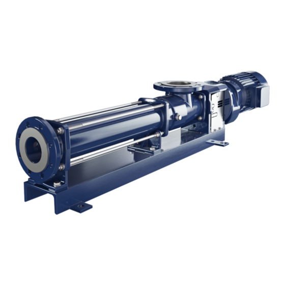
- Page 1 Not Binding Operating and Assembly Instruction Progressive Cavity Pump This operating and assembly instruction is only for general information. Type BN 52-6LS up to 130-6LS Issue 26.06.2017...
-
Page 3: Table Of Contents
Index Index Index Index 1 1 1 1 Safety Safety ..........................................................................................1 1 1 1 Safety Safety..............................General notes Safety and warning notes 1.2.1 Warning notes 1.2.2 Danger symbols 1.2.3 Information symbols Dangers that can be caused by the machine Qualification of the personnel Authorised people 1.5.1... -
Page 4: Table Of Contents
Index Index Index Index Measures before commissioning.................... 14 6.2.1 Checking pipelines 6.2.2 Protective devices on the pump 6.2.3 Electrical / hydraulic connections 6.2.4 Direction of rotation check 6.2.5 Additional devices - optional Initial commissioning/repeated commissioning 6.3.1 Avoiding dry running of the pump 6.3.2 Pressure in the suction and pressure connection De-commissioning... - Page 5 Index Index Index Index Mechanical seal ........................49 9.4.1 Safety 9.4.2 Application conditions and material version 9.4.3 Design 9.4.4 Commissioning 9.4.5 Monitoring during operation 9.4.6 Dismantling of mechanical seal 9.4.7 Reassembly of mechanical seal Spare parts Spare parts ........................................................Spare parts Spare parts............................
-
Page 7: General Notes
Safety General notes Always keep the operating and maintenance instructions close by the machine. If problems cannot be solved with reference to the operating and maintenance instructions, please contact the manufacturer. Observe the following points in addition to these operating and maintenance instructions: •... -
Page 8: Information Symbols
• List item Dangers that can be caused by the machine seepex machines are built in accordance with the state of the art. Nevertheless, there is a residual risk, because the machine works with: • Mechanical movements that pose a danger •... -
Page 9: Tasks And Information For The Owner/Operators
Avoid/limit risks by the use of collective technical protective equipment or by organisational measures at work. Safety and protective devices Prior to start-up, bolt seepex machines onto a concrete foundation so as to ensure stability. Starting and stopping devices must be clearly recognisable. Take appropriate measures to avoid defects. -
Page 10: Designated Use
Safety Designated use • Only use seepex machines if they are in perfect condition and in compliance with the oper- ating and maintenance instructions. • Do not start up the machine unless the system in which the machine is installed is in accor- dance with the provisions of the applicable guidelines and statutory regulations. -
Page 11: General Description
Description of the pump General description seepex pumps are members of the group of rotating displacement pumps. • Characteristic features – Special configuration/arrangement of the rotor and stator pumping elements. – Motion sequence Mode of action and pumping principle of the seepex pump •... -
Page 13: Technical Data
Technical data Data sheet Characteristic Curves Declaration • Data sheet, characteristic curves and declarations are commission specific documents and not part of this not binding operating and assembly instruction. Ausgabe Dokument Blatt A / 29.06.2017 1 (1) OM.TED.XXe issue document sheet... -
Page 15: Safety
Comply with the symbols and notices on the packaging. Remove the screwed connection between the machine and packaging. Remove the machine with a lifting machine/industrial truck. Temporary storage/Corrosion protection • All seepex machines have corrosion protection applied as standard prior to transport. Ausgabe Dokument Blatt D / 27.08.2012 OM.TRA.01e... - Page 16 Property damage can occur due to corrosion. Temporary storage must be in a dry, enclosed, frost-free room in order to provide protec- tion against ambient influences. Contact seepex regarding the necessary corrosion protection for temporary storage. Disposal NOTICE Environmental protection Material damage can occur.
-
Page 17: Dimensions, Weight And Centre Of Gravity
Assembly / Installation Mounting tools / lifting gear CAUTION Pump falling over. Slight injury or damage to property can occur. Adhere to the lifting tool’s starting point. Pay attention to the dimensions, weight and centre of gravity of the pump. ... -
Page 18: Pipelines
Assembly / Installation Power supply of the seepex pump DANGER Supply voltage and power frequency. Death or serious injury will result. Heed type plate on the pump. Pay attention to manufacturer’s directions (chapter 13.). Pay attention to safety regulations. - Page 19 Date of installation: Assembly check carried out on: Please enter operational data: Conveying liquid: Temperature: Fuse level/motor protection or power consumption Frequency control If yes: Supplied by seepex Supplied by customer Frequency: Speed: Power consumption: ________________________________ _______________________________________ Place, date Signature / company stamp...
-
Page 21: Checking Pipelines
Commissioning / De-commissioning Measures before commissioning Note the technical data (chapter 3.). 6.2.1 Checking pipelines Check flange screwed connections (SCH). Check threaded connections (G). NOTICE Ensure the liquid can flow through without obstruction. Malfunction and/or irreparable damage to the pump. ... -
Page 22: Direction Of Rotation Check
Complete failure of the pump. Make sure that the suction-side conveying capacity does not cavitate. If this cannot be guaranteed on the machine side, assemble a seepex dry running protection (TSE). 6.3.2 Pressure in the suction and pressure connection CAUTION High pressure. -
Page 23: Switching Off The Pump
Commissioning / De-commissioning De-commissioning Protect the pump and additional devices against the following: • Frost • Deposit of solids • Sedimentation from the liquid • Corrosion of parts that come into contact with the medium 6.4.1 Switching off the pump DANGER Dangerous voltage. -
Page 24: Preservation/Storage Of The Pump
6.4.4 Preservation/storage of the pump NOTICE Damage to property due to lack of corrosion protection. Property damage can occur due to corrosion. Contact seepex to discuss suitable preservation measures. – State the commission number of the pump. Ausgabe Dokument Blatt C / 02.11.2012... -
Page 25: Pump Down-Time
Acquisition of a set of wearing parts and a set of gaskets. Lubrication Denomination Lubricant Lubricant change in Fill volume operating hours Pin joint seepex special grease 10000 h Pin joint seepex special grease 10000 h Drive Refer to manufacturer's documentation (chapter 13._) Rotor/stator... -
Page 26: Joint Grease
Maintenance 7.2.1 Joint grease NOTICE Other grease types. Malfunction and/or irreparable damage to the joints or the pump. Exclusively use seepex special grease. Inspection Component Interval Action Joints Every 10,000 operating hours Renew joint grease Stator Every week Visual check for leaks... - Page 27 Malfunctions, causes, rectification Refer to technical data (chapter 3.) for application range of the pump. Malfunction Causes Rectification X Static friction between sta- Apply lubricant (liquid soap) tor/rotor too great. between stator and rotor. Incorrect direction of rota- Check direction of rotation tion.
- Page 28 Stator/rotor worn. Dismantle pump and renew defective parts. Joint parts worn. Renew joint parts, use seepex pin joint grease. Suction pipe blocked. Clean the suction pipe. Temperature of pumping Check temperature, use liquid too high. an undersize rotor.
-
Page 29: Dismantling
Dismantling/reassembly 9.1 Pump with Smart Conveying Technology - SCT Range: Size: 52-6LS to 130-6LS Version: New pump Table of contents: 9.1.1 Stator, Rotor - dismantling - SCT 9.1.2 Rotor, stator - reassembly - SCT 9.1.3 Pump - dismantling - SCT 9.1.4 Pump - reassembly - SCT ... - Page 30 Dismantling/reassembly Remove upper adjusting segments (635.o). – Conveying product can escape. Pump with dry-running protection option (TSE) Mount self-tapping screws (658) and hold- ing device (657). Remove upper half of the stator (601.o). – Conveying product can escape. ...
- Page 31 Dismantling/reassembly Tool (WZ/circlip tongs 45°) Spread the circlip (643) wide enough so that it can be released. – Use tool (WZ). Slide circlip (643) towards rotor (600). Slide support ring (682) towards rotor (600). Remove the lock washer (683). –...
- Page 32 Dismantling/reassembly Tool (W29/lifting equipment incl. lashing strap) Tool (W9/mounting lever) Secure rotor (600). – Use tool (W29). Press rotor (600) on the rotor head (640) with tool (W9/mounting lever). – Protect segment mount (671) against possible deformation. – Ensure lock washer (683) is installed.
- Page 33 Dismantling/reassembly Tool (W29/lifting equipment incl. lashing strap) Secure rotor (600). – Use tool (W29). Attach the lower half of the stator (601.u). Press the stator half (601.u) onto the ta- pered surfaces of the segment receiver (671) and align it. ...
- Page 34 Dismantling/reassembly Attach the upper half of the stator (601.o). Align the long side of the upper half of the stator (601.o) to the lower half of the stator (601.u). Pump with dry-running protection option (TSE) • The holding device for the dry running pro- tection (TSE) can get in the way when dis- mantling the adjusting segments (635).
- Page 35 Dismantling/reassembly 9.1.2.3 Smart Stator setting NOTICE Stator is leaky! Damage to property can occur. A gap between the stator halves is not allowed. Alignment of the adjusting segments (635) Align the gap (S2) of the lower adjusting segments (635.u) to the gap (S1) of the upper adjusting segments (635.o).
- Page 36 Dismantling/reassembly Fine adjustment of the pump parameters: Fine adjustments for the pump parameters can be made by evenly adjusting the nuts at the adjusting segments (635). • +10° = increases clamping. • -10° = reduces clamping. Observe the order. –...
- Page 37 Dismantling/reassembly 9.1.3 Pump - dismantling - SCT WARNING Risk of pump tipping or falling. Death or serious injury can occur. Fasten the base plate (GPU) to secure the pump. 9.1.3.1 Preparing the pump for dismantling DANGER Dangerous voltage. Death or serious injury can occur. ...
- Page 38 Dismantling/reassembly Remove upper half of the stator (601.o). – Conveying product can escape. Dismantle adjusting segments (635.u). – Secure adjusting segments (635.u) to prevent them from falling down. Remove lower half of the stator (601.u) smoothly. – Conveying product can escape.
- Page 39 Dismantling/reassembly 9.1.3.5 Segment retainer (671) - dismantling - pressure branch Dismantle the segment retainer (671) on the suction casing (500). Remove the O-ring (731) from the centring recess on the suction casing (ZA, 500). 9.1.3.6 Rotating unit (RTE) – Dismantling with flush connection Tool (W10/dismantling tool) ...
- Page 40 Dismantling/reassembly 9.1.3.7 Rotor (600), coupling rod (400), plug-in shaft (307) - Dismantling Joint (G) dismantling note rotating unit - in- dividual parts (chapter 9.2). 9.1.3.8 Lantern (200)/drive (ANT) - Dismantling Disconnect the drive (ANT) from the lan- tern (200). ...
- Page 41 Dismantling/reassembly 9.1.4.3 Rotating unit (RTE) - Reassembly Push on the shaft seal (SEA). – Note shaft seal reassembly. See chapter 9.4 of the operating and as- sembly instructions. Coat the splash ring (310)/plug-in shaft (307) with pin joint grease. ...
- Page 42 Dismantling/reassembly 9.1.4.6 Segment retainer (671), pressure branch (700) – pre-assembly Remove contaminants such as paint and corrosion from all seal faces/centring re- cesses (ZA). Coat O-ring (731) with soft soap. Insert the O-ring (731) into the centring re- cess on the suction casing (ZA, 500).
- Page 43 Dismantling/reassembly Tool (W29/lifting equipment incl. lashing strap) Secure rotor (600). – Use tool (W29). Attach the lower half of the stator (601.u). Press the stator half (601.u) onto the ta- pered surfaces of the segment receiver (671) and align it. ...
- Page 44 Dismantling/reassembly Attach the upper half of the stator (601.o). Align the long side of the upper half of the stator (601.o) to the lower half of the stator (601.u). Pump with dry-running protection option (TSE) • The holding device for the dry running pro- tection (TSE) can get in the way when dis- mantling the adjusting segments (635).
- Page 45 Dismantling/reassembly 9.1.4.9 Smart Stator setting NOTICE Stator is leaky! Damage to property can occur. A gap between the stator halves is not allowed. Alignment of the adjusting segments (635) Align the gap (S2) of the lower adjusting segments (635.u) to the gap (S1) of the upper adjusting segments (635.o).
- Page 46 Dismantling/reassembly Fine adjustment of the pump parameters: Fine adjustments for the pump parameters can be made by evenly adjusting the nuts at the adjusting segments (635). • +10° = increases clamping. • -10° = reduces clamping. Observe the order. –...
- Page 47 Dismantling/reassembly Rotating unit individual parts 9.2.1 Dismantling 9.2.1.1 Dismantle holding band (406, 407) CAUTION Danger of injury. Parts might be thrown out. Wear safety glasses. Detach holding band loop (SCL). – Use suitable tool (WM). Push out parts of holding band loop (SCL). ...
- Page 48 Dismantling/reassembly Bend (A) the coupling rod (400). Knock guide bushing (403) out. – Use tool (W5). Remove coupling rod (400). 9.2.2 Rotating unit (RTE) – preparing component parts for assembly 9.2.2.1 Prepare rotor head (640) for assembly ...
- Page 49 Dismantling/reassembly 9.2.3 Rotating unit (RTE) – component parts – mounting NOTICE Malfunction of the joints. Malfunction and/or destruction of joints. Replace coupling rod pins (402) and guide bushings (403) jointly. 9.2.3.1 Rotor head (640) – coupling rod (400) – connecting ...
- Page 50 Dismantling/reassembly 9.2.3.2 Mount universal joint sleeve (405) on rotor side Moisten the surface of coupling rod (400) / inner surface of universal joint sleeve (405) with joint grease (maintenance chapter 7.). Slide on universal joint sleeve (405). Remove air from the inside of the joint. –...
- Page 51 Dismantling/reassembly 9.2.3.4 Mount retaining sleeve (401) on drive side Tool (W4/assembly mandrel) Knock back retaining sleeve (401). – Use tool (W4). Rotor (600) unhardened material Secure retaining sleeve (401) in a dis- placed manner (2x180°). – Use suitable tool (WK). Rotor (600) hardened material ...
- Page 53 Dismantling / Reassembly Holding band - assembly 9.3.1 Prepare the holding band Only use prefabricated double-band holding bands may. 9.3.2 Check the holding band • Bent-over holding band (HBD) is in con- tact with holding band loop (SCL) to avoid damaging universal joint sleeve.
-
Page 54: Cant Up The Holding Band
Dismantling / Reassembly 9.3.5 Cant up the holding band Swivel mounting tool (W3) approx. 60° up- wards. Loosen crank (KU) by a half turn. Swivel cutting lever (SH) forward until the pressure piece is lying behind the holding band loop (SCL). - Page 55 Wear suitable protective clothing. Dispose of leakage appropriately. Note applicable regulations when handling hazardous substances. 9.4.2 Operating conditions and material combination • Adjust to the relevant application Design variants you will find at http://www.seepex.com/en/service/downloads/. – Dokument Ausgabe Blatt A / 29.06.2017 OM.SEA.XXe...
- Page 57 Spare parts 10.1 Spare parts list 10.2 Sectional drawing and parts list Ausgabe Dokument Blatt B / 29.03.2011 OM.SZG.02e 1 (1) issue document sheet...
- Page 59 10. Spare parts Ordering spare parts Spare parts Commission number ............The commission number and type are printed on the type plate of your SEEPEX machine. Type ..................After placing the order, you will receive an Request order confirmation and deadline before the parts are shipped.
- Page 60 10. Spare parts Order spare parts or complete packages tailored to your pump type. Spare parts Plug-in shaft and shaft seal Component Qty. Packing ring (set) * Plug-in shaft Plug-in shaft pin Splash ring Flushing ring * Mechanical seal * Coupling rod and joint parts Component Qty.
- Page 61 10. Spare parts Pumping elements Component Qty. Rotor Stator half Rotor head O-ring Clirclip Support ring Locking plate Miscellaneous parts Component Qty. Casing gasket Sealing ring Seal * Sealing ring * Sealing ring Joint grease (GF) = 300 g (~ 315 cm³) for the required grease quantity refer to chapter 10 Complete packages Small wearing parts package...
- Page 62 10. Spare parts Large wearing parts package consisting of: Qty. 1 x Packing ring (set) (301) * 1 x Plug-in shaft (307) 1 x Splash ring (310) 1 x Flushing ring (311) * 1 x Mechanical seal (330) * 1 x Coupling rod (400) 2 x Retaining sleeve (401) 2 x Coupling rod pin (402) 4 x Guide bushing (403)
- Page 63 11. Special tools Ordering special tools Special tools Commission number ............The commission number and type are printed on the type plate of your SEEPEX machine. Type ..................Request After placing the order, you will receive an order confirmation and deadline before the parts are shipped.
- Page 64 11. Special tools Your order Order special tools tailored to your pump type. Tool no. Denomination For assembly of Order no. Packing puller Packing* Mounting tool Holding band Assembly mandrel Joint Drift Joint Mounting lever General Dismantling tool Plug-in shaft Hoisting device incl.
- Page 65 Associated documents 12.1 Accessories/Technical information • Accessories and technical information are commission specific documents not part of this not binding operating and assembly instruction. Ausgabe Dokument Blatt 1 (1) A / 29.06.2017 OM.ZUG.XXd issue document sheet...
- Page 67 Appendix 13.1 Manufacturer's and supplier's documents • Manufacturer's and supplier's documents are commission specific documents and not part of this not binding operating and assembly instruction. Ausgabe Dokument Blatt A / 29.06.2017 OM.MDS.XXe 1 (1) issue document sheet...
- Page 70 NSW 2259 Nam Seksyen 51 Tel +81.46.2595931 Tel +61.2.43554500 Fax +81.46.2595941 46050 Petaling Jaya Selengor Fax +61.2.43554022 info.jp@seepex.com Darul Ehsan info.au@seepex.com Tel +60.3.88009988 seepex.m@seepex.com More SEEPEX sales partnes in Europe, America, Asia, Africa and Oceania you willl find on our website.
Need help?
Do you have a question about the BN 52-6LS and is the answer not in the manual?
Questions and answers