
Related Manuals for Seepex BN 2-12S


Summary of Contents for Seepex BN 2-12S
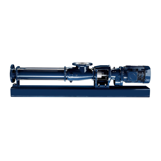
- Page 1 Not Binding Operating and Assembly Instruction Progressive Cavity Pump This operating and assembly instruction is only for general information. Type BN 2-12S to 17-12S Issue 26.06.2017...
- Page 3 Index Index Index Index 1 1 1 1 Safety Safety ..........................................................................................1 1 1 1 Safety Safety..............................Notes on these instructions Safety-related Information Designated use Foreseeable misuse Structure of warning notes 1.5.1 Warning levels 1.5.2 Warning symbols Qualification of the personnel Tasks, notes for the owners, operators and technicians Personal protective equipment Safety and protective devices...
- Page 4 Index Index Index Index 6 6 6 6 Commissioning / De-Commissioning Commissioning / De-Commissioning Commissioning / De-Commissioning Commissioning / De-Commissioning................................................................................17 Commissioning report......................17 Measures before commissioning.................... 19 6.2.1 Checking pipelines 6.2.2 Protective devices on the pump 6.2.3 Electrical / hydraulic connections 6.2.4 Direction of rotation check...
- Page 5 Index Index Index Index...
- Page 7 These operating and assembly instructions are valid exclusively for ma- chines with the commission no. specified on the cover sheet. • The operating and assembly instructions are correlated with the SEEPEX machine by means of the commission no. on the type plate (TYS). Figure similar...
- Page 8 1. Safety 1.1.3 Symbols, notes and abbreviations 1.1.3.1 Information symbols Symbol Application Instruction/measure supplementary instruction/measure List item Information Cross-reference 1.1.3.2 Abbreviations Abbreviations facilitate readability in drawings. Abbreviations are explained below: Abbrevia- Designation Abbrevia- Designation tion tion Drive Terminal Lashing points...
- Page 9 1. Safety Safety-related Information SEEPEX machines are built in accordance with the state of the art. Neverthe- less, there is a residual risk, because the machine works with: • Mechanical movements that pose a danger • Electrical voltages and currents Designated use SEEPEX machines are individually configured.
- Page 10 1. Safety DANGER Type and source of danger. Possible consequences. Measures to avert the danger. Preceding warning notes with warning or mandatory signs Specific dangers are identified with additional warning or mandatory signs. Example: DANGER Type and source of danger. Possible consequences.
- Page 11 1. Safety Property damage NOTICE NOTICE is used when the situation is not associated with personal injury. 1.5.2 Warning symbols In these operating and assembly instructions and on the machine, there are warning symbols. Ensure that these warning symbols are complied with. ...
- Page 12 1. Safety Qualification of the personnel Detailed technical knowledge is essential for performing any work on the machine, in order to be able to independently recognise and avoid potential dangers. Activity Person proven knowledge Instruction of person- Owner Knowledge of safety regulations ...
- Page 13 1. Safety Tasks, notes for the owners, operators and technicians Do not work on the machine or plant unless it is at a standstill and de- pressurised. Switch off the main switch and pull out the power plug before starting work on live components.
- Page 14 Possible contact with aggressive media Safety and protective devices Before commissioning, bolt SEEPEX machines to a suitable foundation to ensure stability. Start-stop equipment must be clearly recognisable. In order to avoid errors, the operator must arrange corresponding measures.
- Page 15 Description of the pump General description seepex pumps are members of the group of rotating displacement pumps. • Characteristic features – Special configuration/arrangement of the rotor and stator pumping elements. – Motion sequence Mode of action and pumping principle of the seepex pump •...
- Page 17 Technical data Data sheet Characteristic Curves Declaration • Data sheet, characteristic curves and declarations are commission specific documents and not part of this not binding operating and assembly instruction. Ausgabe Dokument Blatt A / 29.06.2017 1 (1) OM.TED.XXe issue document sheet...
- Page 19 Comply with the symbols and notices on the packaging. Remove the screwed connection between the machine and packaging. Remove the machine with a lifting machine/industrial truck. Temporary storage/Corrosion protection • All seepex machines have corrosion protection applied as standard prior to transport. Ausgabe Dokument Blatt D / 27.08.2012 OM.TRA.01e...
- Page 20 Property damage can occur due to corrosion. Temporary storage must be in a dry, enclosed, frost-free room in order to provide protec- tion against ambient influences. Contact seepex regarding the necessary corrosion protection for temporary storage. Disposal NOTICE Environmental protection Material damage can occur.
-
Page 21: Assembly & Installation
5. Assembly, installation Assembly, installation Safety during assembly and installation CAUTION Risk of injury due to improper assembly and installation of the machine. Improper installation of the machine can lead to minor injuries and significant damage to property. Before starting work, ensure there is sufficient space for assembly. ... - Page 22 5. Assembly, installation Ensure that the drives are seated correctly. – Shifting of the drive during transport/installation of the pump must be compensated for by aligning/securing the drive. Attach protective devices and make sure they are functioning. Adjust and connect pipelines ...
- Page 23 Date of installation: Assembly check carried out on: Please enter operational data: Conveying liquid: Temperature: Fuse level/motor protection or power consumption Frequency control If yes: Supplied by seepex Supplied by customer Frequency: Speed: Power consumption: ________________________________ _______________________________________ Place, date Signature / company stamp...
- Page 25 Commissioning / De-commissioning Measures before commissioning Note the technical data (chapter 3.). 6.2.1 Checking pipelines Check flange screwed connections (SCH). Check threaded connections (G). NOTICE Ensure the liquid can flow through without obstruction. Malfunction and/or irreparable damage to the pump. ...
- Page 26 Complete failure of the pump. Make sure that the suction-side conveying capacity does not cavitate. If this cannot be guaranteed on the machine side, assemble a seepex dry running protection (TSE). 6.3.2 Pressure in the suction and pressure connection CAUTION High pressure.
- Page 27 Commissioning / De-commissioning De-commissioning Protect the pump and additional devices against the following: • Frost • Deposit of solids • Sedimentation from the liquid • Corrosion of parts that come into contact with the medium 6.4.1 Switching off the pump DANGER Dangerous voltage.
- Page 28 6.4.4 Preservation/storage of the pump NOTICE Damage to property due to lack of corrosion protection. Property damage can occur due to corrosion. Contact seepex to discuss suitable preservation measures. – State the commission number of the pump. Ausgabe Dokument Blatt C / 02.11.2012...
-
Page 29: Maintenance
Acquisition of a set of wearing parts and a set of gaskets. Lubrication Denomination Lubricant Lubricant change in Fill volume operating hours Pin joint seepex special grease 10000 h Pin joint seepex special grease 10000 h Drive Refer to manufacturer's documentation (chapter 13._) Rotor/stator... - Page 30 Maintenance 7.2.1 Joint grease NOTICE Other grease types. Malfunction and/or irreparable damage to the joints or the pump. Exclusively use seepex special grease. Inspection Component Interval Action Joints Every 10,000 operating hours Renew joint grease Stator Every week Visual check for leaks...
- Page 31 Malfunctions, causes, rectification Refer to technical data (chapter 3.) for application range of the pump. Malfunction Causes Rectification X Static friction between sta- Apply lubricant (liquid soap) tor/rotor too great. between stator and rotor. Incorrect direction of rota- Check direction of rotation tion.
- Page 32 Stator/rotor worn. Dismantle pump and renew defective parts. Joint parts worn. Renew joint parts, use seepex pin joint grease. Suction pipe blocked. Clean the suction pipe. Temperature of pumping Check temperature, use liquid too high. an undersize rotor.
- Page 33 9.1 Dismantling All work steps and tools required for dismantling are specified in this chapter. 3-D ANIMATIONS In addition to your SEEPEX operating and assembly instructions, 3-D anima- tions of the individual dismantling steps are available. Start animations For printed operating and assembly instructions, scan the...
- Page 35 9.1 Dismantling 9.1 Dismantling 9.1.1 Keep tools ready for the dismantling Recommended tools Keep the listed tools ready (not part of the delivery scope): Illustration Denomination Hammer Set allen keys Set ring spanners size 10 - size 30 Set fork spanners size 10 - size 30 Metal saw (WH) Screwdriver (WS) Chisel (WM)
- Page 36 9.1 Dismantling Illustration Denomination Mounting lever (W9) Dismantling tool (W10) Recommended auxiliary materials Keep the auxiliary materials listed available (not included in the scope of delivery): Lubricant (GM) NOTICE Damage to property due to inadequate lubricants (GM). Damage to components. Contamination of the conveying medium. ...
- Page 37 9.1 Dismantling 9.1.3.1 Dismantle stator (601) Dismantle dry-running protection device (TSE) (optional) Damage to pump sided parts of the dry- running protection device (TSE) during dismantling the stator. Before dismantling the stator, remove all pump sided parts of the dry-running protection device (TSE).
- Page 38 9.1 Dismantling Turn kinetic ring recess (670) until adjusting segment (635) is exposed. Remove adjusting segment (635). Turn kinetic ring recess (670) until adjusting segment (635) is exposed. Remove adjusting segment (635). Remove upper stator half (601). ...
- Page 39 9.1 Dismantling Turn kinetic ring recess (670) until adjusting segment (635) is exposed. Remove adjusting segment (635). Remove lower stator half (601). 9.1.3.2 Dismantle rotor (600) Prop up rotor (600) with support (S). Slide circlip (643) onto rotor (600). –...
- Page 40 9.1 Dismantling Remove the lock washer (683). – Use a suitable tool (WS). Remove rotor (600) from rotor head (640). Remove support (S). Remove kinetic rings (670) from suction casing (500) and pressure branch (700). Remove circlip (643), support ring (682) and O-ring (642) from the rotor (600).
- Page 41 9.1 Dismantling 9.1.3.3 Dismantle pressure branch (700) Dismantle screw fitting (SCH). Remove pressure branch (700). 9.1.3.4 Dismantle suction casing (500) Dismantle screw fitting (SCH) from trestle (607). Remove screw fitting (506, 507, 509). Remove suction casing (500) and casing gasket (501).
- Page 42 9.1 Dismantling Raise/reposition splash ring (310) to remove plug-in shaft pin (309). Eject plug-in shaft pin (309). – Use a suitable tool (WS). Assemble tool (W10) as contact surface for mounting lever (W9). Pull off rotating unit (RTE) with shaft seal (SEA) from output shaft of drive (ANT).
- Page 43 9.1 Dismantling Dismantle tool (W10). Remove splash ring (310) and shaft seal casing (SEA) from plug-in shaft (307). – See dismantling of shaft seal (SEA) ( chapter 9.4). 9.1.3.6 Remove rotor head (640), coupling rod (400), plug-in shaft (307) Dismantle holding band (406, 407) ...
- Page 44 9.1 Dismantling Knock out coupling rod pin (402). – Use tool (W5). Bend rotor head (640). Knock out guide bushings (403). – Use tool (W5). Remove rotor head (640) and retaining sleeve (401) from coupling rod (400). ...
- Page 45 9.1 Dismantling Separate joint - drive side For easier dismantling, apply lubricant (GM) to the interior of the universal joint sleeve (405) and the outer surface of the coupling rod (400). Remove universal joint sleeve (405) from coupling rod (400). ...
- Page 46 9.1 Dismantling 9.1.3.7 Dismantle lantern (200) and drive (ANT) Dismantle screw fitting (210, 212, 213). Remove drive (ANT) from lantern (200). Dismantle screw fitting (SCH). Remove lantern (200) from base plate (GPU). A / 07.11.2019 - OM.SCT.BN.S03EN 13/36...
- Page 47 9.2 Reassembly All work steps and tools required for reassembly are specified in this chapter. 3-D ANIMATIONS In addition to your SEEPEX operating and assembly instructions, 3-D anima- tions of the individual assembly steps are available. Start animations For printed operating and assembly instructions, scan the...
- Page 48 9.2 Reassembly 9.2 Reassembly 9.2.1 Keep tools ready for assembly Recommended tools Keep the listed tools ready (not part of the delivery scope): Illustration Denomination Hammer Set allen keys Set ring spanners size 10 - size 30 Set fork spanners size 10 - size 30 Screwdriver (WS) Pliers (WFZ) Centre punch (WK)
- Page 49 Soft soap (GS) Anti-seize graphite petroleum (GC) SEEPEX joint grease (GF) Kinetic ring grease (KF) - SEEPEX BIO 10206 NOTICE Damage to property due to inadequate lubricants (GM). Damage to components. Contamination of the conveying medium.
- Page 50 9.2 Reassembly Malfunction of the joints. Malfunction and/ or destruction of the joints. Renew coupling rod pin (402) and guide bushings (403) together. Drive in guide bushings (403) (Depth X = 2/3). – Use tool (W4). 9.2.2.2 Prepare coupling rod (400) for assembly ...
-
Page 51: Assemble Pump
9.2 Reassembly Check the holding band (406, 407) – Bent-over holding band (406, 407) is in contact with holding band loop (SCL) to avoid damaging universal joint sleeve (405). – Press on holding band (406, 407) using tool (WFZ) if necessary. 9.2.3 Assemble pump Risk of injury due to lack of stability of the pump. - Page 52 9.2 Reassembly 9.2.3.2 Assemble rotor head (640), coupling rod (400), plug-in shaft (307) Connect rotor head (640) with coupling rod (400) Fill rotor head (640) with SEEPEX joint grease (GF). – Use tool (WF). Slide coupling rod (400) into rotor head (640).
- Page 53 Assemble universal joint sleeve (405) - rotor-side For simpler assembly of the universal joint sleeve (405), moisten the outer surface of coupling rod (400) with SEEPEX joint grease (GF). Fill interior of universal joint sleeve (405) with SEEPEX joint grease (GF).
- Page 54 9.2 Reassembly Tighten holding band (406, 407) - rotor-side – Insert holding band (406, 407) into tool (W3). – Clamp holding band firmly using eccentric lever (EX). – Turn crank (KUL) until the holding band (406, 407) is tensioned and is in contact with holding band loop (SCL).
- Page 55 9.2 Reassembly Shear off holding band (406, 407) for material design stainless steel, corrosion-resistant steel Universal joint sleeve can be damaged by hammering and striking. Joint grease (GF) can leak out. Avoid hammering or striking the universal joint sleeve. Refer to the technical data ( chapter 3) for the material design.
- Page 56 (405), lubricate the outer surface of coupling rod (400) with SEEPEX joint grease (GF). Slide holding bands (406, 407) and universal joint sleeve (405) onto coupling rod (400). Fill interior of joint head with SEEPEX joint grease (GF). – Use tool (WF).
- Page 57 Assemble universal joint sleeve (405) - drive side Fill the inside of universal joint sleeve (405) with SEEPEX joint grease (GF). – For filling grade of SEEPEX joint grease (GF), refer to the maintenance document ( chapter 7). –...
- Page 58 9.2 Reassembly Damage of universal joint sleeve due to sharp tools. Leak in universal joint sleeve. Ventilate inner area of joint by lifting the universal joint sleeve (405). – Use a suitable tool (WS). Assemble holding band - drive-side ...
- Page 59 9.2 Reassembly False Holding band (406, 407) too loose, can slip off. Incorrect The holding band (406, 407) is too tight, universal joint sleeve will be damaged/sheared off. Cant up the holding band (406, 407). Swivel mounting tool (W3) approx. 60° upwards.
- Page 60 9.2 Reassembly Cut off holding band (406, 407) for material design stainless steel, heat-resistant steel Universal joint sleeve can be damaged by hammering and striking. Joint grease (GF) can leak out. Avoid hammering or striking the universal joint sleeve. Refer to the technical data ( chapter 3) for the material design.
- Page 61 9.2 Reassembly Moisten output shaft of drive (ANT) with anti- seize graphite petroleum (GC) for easier assembly of the rotating unit (RTE). Push rotating unit (RTE) onto output shaft of the drive (ANT). Moisten plug-in shaft pin (309) with anti-seize graphite petroleum (GC) and insert into the plug- in shaft (307).
- Page 62 9.2 Reassembly Assemble the flush connection (SSU) (optional) Assemble flush connection (SSU). 9.2.3.4 Assemble suction casing (500) Push on casing gasket (501). Assemble and align suction casing (500) with screw fitting (506, 507, 509). – Use spirit level (WW). ...
- Page 63 518 mm 9.2.3.6 Assemble rotor (600) Moisten inner surfaces of kinetic rings (670) with SEEPEX kinetic ring grease. Slide kinetic rings (670) onto suction casing (500) and pressure branch (700). Insert O-ring (642) into circumferential groove of the rotor (600).
- Page 64 9.2 Reassembly Moisten inner surface of rotor head (640) with anti-seize graphite petroleum (GC). Slide rotor (600) into rotor head (640). – Note position of the groove (X). Prop up rotor (600) with support (S). Press rotor (600) into the rotor head (640). –...
- Page 65 9.2 Reassembly 9.2.3.7 Assemble stator (601) CAUTION Risk of injury from moving and falling pump parts. Body parts can get crushed. Turn kinetic rings (670) only on the outer surface. Secure lower adjusting segments (635) and stator half (601) to prevent them from falling. NOTICE Moisten stator outer surfaces with soft soap (GS).
- Page 66 9.2 Reassembly Turn recess in kinetic rings (670) until adjusting segment (635) can be assembled. Insert guide bolt (636) for adjusting segment (635) into groove on pressure branch (700) and suction casing (500). Observe the segment order (A-A). ...
- Page 67 9.2 Reassembly Press stator half (601) onto tapered surfaces of pressure branch (700) and suction casing (500) and align. – Avoid damage to stator surfaces. Align long side of upper stator half (601) with lower stator half (601). ...
- Page 68 9.2 Reassembly Assembling the dry-running protection device (TSE) (optional) Assemble dry-running protection device (TSE). – Refer to chapter Options and Additional accessories ( chapter 12.1). 9.2.3.8 Smart Stator setting NOTICE Gap between stator halves due to inappropriate setting. Possible leakage at stator. ...
- Page 69 9.2 Reassembly Adjusting segments (635) - Precision setting Observe distance (X): – Use tool (WG). Size Distance (X) 2-12S 20.5 mm 5-12S 20.5 mm 10-12S 25.5 mm 17-12S 25.5 mm A / 07.11.2019 - OM.SCT.BN.S03EN 36/36...
- Page 71 Wear suitable protective clothing. Dispose of leakage appropriately. Note applicable regulations when handling hazardous substances. 9.4.2 Operating conditions and material combination • Adjust to the relevant application Design variants you will find at http://www.seepex.com/en/service/downloads/. – Dokument Ausgabe Blatt A / 29.06.2017 OM.SEA.XXe...
- Page 73 Spare parts 10.1 Spare parts list 10.2 Sectional drawing and parts list Ausgabe Dokument Blatt B / 29.03.2011 OM.SZG.02e 1 (1) issue document sheet...
-
Page 75: Ordering Spare Parts
10. Spare parts Ordering spare parts Spare parts Commission number ............The commission number and type are printed on the type plate of your SEEPEX machine. Type ..................After placing the order, you will receive an Request order confirmation and deadline before the parts are shipped. - Page 76 10. Spare parts Order spare parts or complete packages tailored to your pump type. Spare parts Plug-in shaft and shaft seal Component Qty. Packing ring (set) * Plug-in shaft Plug-in shaft pin Splash ring Flushing ring * Mechanical seal * Coupling rod and joint parts Component Qty.
- Page 77 10. Spare parts Pumping elements Component Qty. Rotor Stator half Rotor head O-ring Clirclip Support ring Locking plate Miscellaneous parts Component Qty. Casing gasket Sealing ring Seal * Sealing ring * Sealing ring Joint grease (GF) = 300 g (~ 315 cm³) for the required grease quantity refer to chapter 10 Complete packages Small wearing parts package...
- Page 78 10. Spare parts Large wearing parts package consisting of: Qty. 1 x Packing ring (set) (301) * 1 x Plug-in shaft (307) 1 x Splash ring (310) 1 x Flushing ring (311) * 1 x Mechanical seal (330) * 1 x Coupling rod (400) 2 x Retaining sleeve (401) 2 x Coupling rod pin (402) 4 x Guide bushing (403)
-
Page 79: Special Tools
11. Special tools Ordering special tools Special tools Commission number ............The commission number and type are printed on the type plate of your SEEPEX machine. Type ..................Request After placing the order, you will receive an order confirmation and deadline before the parts are shipped. - Page 80 11. Special tools Your order Order special tools tailored to your pump type. Tool no. Denomination For assembly of Order no. Qty. Packing puller Packing Mounting tool Holding band Assembly mandrel Joint Drift Joint Mounting lever General Dismantling tool Plug-in shaft __________________________________ _______________________________________ Place, date...
-
Page 81: Associated Documents
Associated documents 12.1 Accessories/Technical information • Accessories and technical information are commission specific documents not part of this not binding operating and assembly instruction. Ausgabe Dokument Blatt 1 (1) A / 29.06.2017 OM.ZUG.XXd issue document sheet... - Page 83 Appendix 13.1 Manufacturer's and supplier's documents • Manufacturer's and supplier's documents are commission specific documents and not part of this not binding operating and assembly instruction. Ausgabe Dokument Blatt A / 29.06.2017 OM.MDS.XXe 1 (1) issue document sheet...
- Page 86 Tuggerah Business Park Tel +81.46.2595931 NSW 2259 Fax +81.46.2595941 46050 Petaling Jaya Tel +61.2.43554500 info.jp@seepex.com Selengor Darul Ehsan Fax +61.2.43554022 Tel +60.3.88009988 info.au@seepex.com seepex.m@seepex.com More SEEPEX sales partnes in Europe, America, Asia, Africa and Oceania you willl find on our website.
Need help?
Do you have a question about the BN 2-12S and is the answer not in the manual?
Questions and answers