Table of Contents
Advertisement
Quick Links
Operating instructions
Passive distribution module
Operating instructions. . . . . . . . . . . . .pages 1 to 8
EN
Translation of the original operating instructions
Content
1
1.1 Function . . . . . . . . . . . . . . . . . . . . . . . . . . . . . . . . . . . . . . . . . . . . . .1
1.2 Target group: authorised qualiied personnel. . . . . . . . . . . . . . . . . .1
1.3 Explanation of the symbols used . . . . . . . . . . . . . . . . . . . . . . . . . . .1
1.4 Appropriate use . . . . . . . . . . . . . . . . . . . . . . . . . . . . . . . . . . . . . . . .1
1.5 General safety instructions . . . . . . . . . . . . . . . . . . . . . . . . . . . . . . .1
1.6 Warning about misuse . . . . . . . . . . . . . . . . . . . . . . . . . . . . . . . . . . .1
1.7 Exclusion of liability . . . . . . . . . . . . . . . . . . . . . . . . . . . . . . . . . . . . .2
2
2.1 Ordering code . . . . . . . . . . . . . . . . . . . . . . . . . . . . . . . . . . . . . . . . .2
2.2 Destination and use . . . . . . . . . . . . . . . . . . . . . . . . . . . . . . . . . . . . .2
2.3 Technical data . . . . . . . . . . . . . . . . . . . . . . . . . . . . . . . . . . . . . . . . .2
3
3.1 General mounting instructions . . . . . . . . . . . . . . . . . . . . . . . . . . . . .3
3.2 Dimensions . . . . . . . . . . . . . . . . . . . . . . . . . . . . . . . . . . . . . . . . . . .3
3.3 Accessories . . . . . . . . . . . . . . . . . . . . . . . . . . . . . . . . . . . . . . . . . . .3
4
4.1 General information for electrical connection. . . . . . . . . . . . . . . . . .3
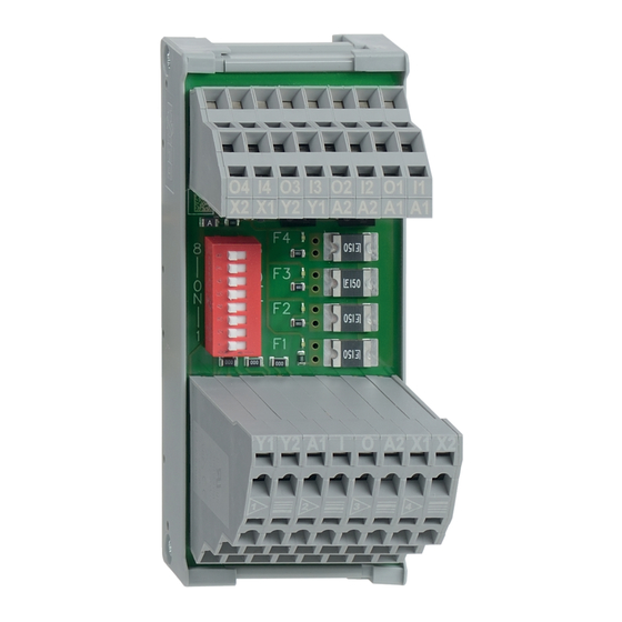
4.2 LED indicators and fuse elements . . . . . . . . . . . . . . . . . . . . . . . . . .3
4.3 Pin assignment of module connection . . . . . . . . . . . . . . . . . . . . . . .4
4.4 Pin assignment of 2 level terminal . . . . . . . . . . . . . . . . . . . . . . . . . .5
4.5 Pin assignment of 4 level terminal . . . . . . . . . . . . . . . . . . . . . . . . . .5
4.6 DIP switch coniguration . . . . . . . . . . . . . . . . . . . . . . . . . . . . . . . . .5
4.7 Wiring example . . . . . . . . . . . . . . . . . . . . . . . . . . . . . . . . . . . . . . . .6
5
5.1 Functional testing. . . . . . . . . . . . . . . . . . . . . . . . . . . . . . . . . . . . . . .8
5.2 Maintenance . . . . . . . . . . . . . . . . . . . . . . . . . . . . . . . . . . . . . . . . . .8
6
6.1 Disassembly. . . . . . . . . . . . . . . . . . . . . . . . . . . . . . . . . . . . . . . . . . .8
6.2 Disposal . . . . . . . . . . . . . . . . . . . . . . . . . . . . . . . . . . . . . . . . . . . . . .8
1. About this document
1.1 Function
These operating instructions provide all the information required for
mounting, commissioning, safe operation and also disassembly of
the device. The operating instructions must be available in a legible
condition and a complete version in the vicinity of the device.
1.2 Target group: authorised qualified personnel
All operations described in this operating instructions manual must
be carried out by trained specialist personnel, authorised by the plant
operator only.
Please make sure that you have read and understood these operating
instructions and that you know all applicable legislations regarding
occupational safety and accident prevention prior to installation and
putting the component into operation.
The machine builder must carefully select the harmonised standards
to be complied with as well as other technical specifications for the
selection, mounting and integration of the components.
1.3 Explanation of the symbols used
Information, hint, note:
This symbol is used for identifying useful additional information.
Caution: Failure to comply with this warning notice could
lead to failures or malfunctions.
Warning: Failure to comply with this warning notice could
lead to physical injury and/or damage to the machine.
1.4 Appropriate use
The products described in these operating instructions are developed to
execute safety-related functions as part of an entire plant or machine. It
is the responsibility of the manufacturer of a machine or plant to ensure
the correct functionality of the entire machine or plant.
The passive distribution module may only be used in accordance
with the following versions or for the applications authorised by the
manufacturer. Detailed information regarding the range of applications
can be found in the chapter "Product description".
1.5 General safety instructions
The user must observe the safety instructions in this operating
instructions manual, the country-specific installation standards as well
as all prevailing safety regulations and accident prevention rules.
Further technical information can be found in the Schmersal
catalogues or in the online catalogue on the Internet:
www.schmersal.net.
The information contained in this operating instructions manual is
provided without liability and is subject to technical modifications.
There are no residual risks, provided that the safety instructions as well
as the instructions regarding mounting, commissioning, operation and
maintenance are observed.
1.6 Warning about misuse
In the event of improper or unintended use or tampering,
use of the passive distribution module could expose persons
to danger or cause damage to the machine or system
components.
EN
PDM-IOP-4CC-IOP
1
Advertisement
Table of Contents

Subscribe to Our Youtube Channel
Related Manuals for schmersal PDM-IOP-4CC-IOP


Summary of Contents for schmersal PDM-IOP-4CC-IOP
- Page 1 2.3 Technical data .........2 Further technical information can be found in the Schmersal...
- Page 2 4 electronic safety switchgear units with parallel Rated operating voltage U 24 VDC IO signals manufactured by SCHMERSAL. It serves to connect up to 4 Operating current I safety switchgear units in series. - Distribution module (external fuse needed):...
- Page 3 Operating instructions Passive distribution module PDM-IOP-4CC-IOP 3. Mounting 4. Electrical connection 3.1 General mounting instructions 4.1 General information for electrical connection The distribution module is designed to be mounted in a switch cabinet. The module can be attached to a standard 35 mm rail in accordance The electrical connection may only be carried out by with EN 60715.
- Page 4 Operating instructions Passive distribution module PDM-IOP-4CC-IOP 4.3 Pin assignment of module connection 2 level terminal Input and output signals of safety switchgear units Safety signals and supply voltage POWER 4 level terminal Y1 Y2 A1 O A2 X1 X2 Safety switchgear connection 4...
- Page 5 Operating instructions Passive distribution module PDM-IOP-4CC-IOP 4.4 Pin assignment of 2 level terminal 4.6 DIP switch configuration The position of the DIP switch is shown in black. Input and output signals of safety switchgear Diagnostic output device 4 Module in centre of series wiring...
- Page 6 Operating instructions Passive distribution module PDM-IOP-4CC-IOP 4.7 Wiring example OUT 1 OUT 2 OUT 3 IN 1 IN 2 IN 3 OUT 4 OUT 5 IN 4 IN 5 OUT 6 OUT 7 OUT 8 OUT 9 IN 6 IN 7...
- Page 7 Operating instructions Passive distribution module PDM-IOP-4CC-IOP Y2 Y1 A2 A1 O4 O3 O2 O1 I4 I3 I2 I1 A1 A2 X1 X2 Y2 Y1 A2 A1 O4 O3 O2 O1 I4 I3 I2 I1 A1 A2 X1 X2 - Module in middle...
- Page 8 The passive distribution module is to be disposed of in the correct manner as per the national regulations and legislation. K. A. Schmersal GmbH & Co. KG Möddinghofe 30, D - 42279 Wuppertal Postfach 24 02 63, D - 42232 Wuppertal...
Need help?
Do you have a question about the PDM-IOP-4CC-IOP and is the answer not in the manual?
Questions and answers