
Subscribe to Our Youtube Channel
Related Manuals for schmersal PSCBR-C-100 Series


Summary of Contents for schmersal PSCBR-C-100 Series
- Page 1 Installation manual Installation Manual PSCBR-C-100 Series PSCBR-E-133-12DI-2DIO-8RO Page 1 of27...
- Page 2 However, we would like to point out, that this document cannot always be updated at the same time as the technical further development of the products. Information and specifications can be changed at any time. Please keep yourself informed about the current version under www.schmersal.com.br Devices of the ACE Schmersal Eletroeletrônica Industrial Ltda.
-
Page 3: Table Of Contents
Installation manual Table of Contents IMPORTANT NOTES ..................4 Definitions ............................4 Co-valid documents ..........................4 Abbreviations used ..........................5 SAFETY REGULATIONS ..................6 Operation and service ......................... 6 Transportation/storage ........................6 DEVICE TYPES ....................7 Characteristic data of device ........................ 7 Identification ............................ -
Page 4: Important Notes
The system software “SafePLC” serves the purpose of configuring and programming PSCBR-C-100 modules. The modules of the PSCBR-C-100 series are internally built up of two independent processing units. In the following these are referred to as system A and system B. -
Page 5: Abbreviations Used
Installation manual Abbreviations used Abbreviation Meaning Alternating voltage Instruction list ELIA Employer's liability insurance association Clock (cycle) Central Processing Unit Direct voltage DI1..DI14 Digital Input Deutsches Institut für Normung (German Institute for Standardization) Digital Output Emergency Monitoring Unit Electromagnetic compatibility Emergency Limit Control European Standard HISIDE... -
Page 6: Safety Regulations
Installation manual 2 Safety regulations Intended use You can only operate the PSCBR-E-133-12DI-2DIO-8RO module with an PSCBR-C-100. This means that the same safety regulations apply as with the PSCBR-C-100 module. Operation and service The module must always be de-energized before installation and removal, or before disconnecting signal lines. -
Page 7: Device Types
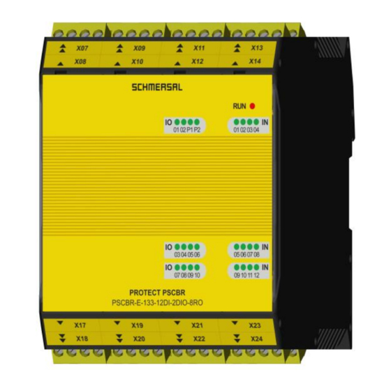
Installation manual 3 Device types Characteristic data of device Type designation Device design Design of module with the following periphery: digital inputs (DI 1-4 and DI8-12 OSSD) I/Os optionally configurable as an input or output secure relay outputs pulse outputs signal outputs status LEDs for inputs status LEDs for I/O/relay output... -
Page 8: Identification
Installation manual Identification The type plate is located on the left side wall of the module and contains the following information: Type designation Part number Serial number Identification of hardware release Identification of software release Safety category Input characteristics Output characteristics Page 8 of27... -
Page 9: Connection And Installation
Installation manual 4 Connection and installation General notes on installation Strictly follow the safety regulations when installing! Type of protection IP20 Route all signal lines for the interfacing of digital inputs and contact monitoring separately. In any case isolate 230VAC voltages from low voltage lines, if these voltages are used in connection with the application. -
Page 10: Installation And Assembly Of The Pscbr Module
Installation manual Installation and assembly of the PSCBR module The module is solely to be installed in control cabinets with a degree of protection of at least IP54. The modules must be vertically fastened on a top hat rail. The ventilation slots must be kept unobstructed, to ensure adequate air circulation inside the module. -
Page 11: Assembling The Modules
Installation manual 4.4 Assembling the modules The modules are mounted on C-standard rails by means of snap-on latches. 4.4.1 Assembly on C-rail The devices are inserted into the rail under an oblique angle and then snapped on downwards. For disassembling use a screwdriver, insert it into the slot of the downwards pointing latch and then move it up. -
Page 12: Assembly On Backplane Bus
Installation manual 4.4.2 Assembly on backplane bus After assembling the backplane bus, you can install the device. For this purpose insert the module from above into the plug connection under a oblique angle and snap it onto the C-rail. Insert the module from above under an oblique angle. Snap-on downwards on to the C-rail. - Page 13 Installation manual The backplane plug connection can later be extended. The system configuration can thus be extended by additional modules. Snap the backplane bus element into the C-rail and insert it into the counter-piece by sliding it sideways. Page 13 of27...
-
Page 14: Terminal Assignment
Installation manual Terminal assignment Terminal Designation Function X07:1 K1/11 Readback contact relay 1 X07:2 K1/12 Readback contact relay 1 X07:3 K2/11 Readback contact relay 2 X07:4 K2/12 Readback contact relay 2 X08:1 K3/11 Readback contact relay 3 X08:2 K3/12 Readback contact relay 3 X08:3 K4/11 Readback contact relay 4... - Page 15 Installation manual X19:1 K5.1 Relay output 5 X19:2 K5.2 Relay output 5 X19:3 K6.1 Relay output 6 X19:4 K6.2 Relay output 6 X20:1 K7.1 Relay output 7 X20:2 K7.2 Relay output 7 X20:3 K8.1 Relay output 8 X20:4 K8.2 Relay output 8 X21:1 Not used X21:2...
-
Page 16: Wiring Of Outputs
Installation manual 5 Wiring of outputs General specifications for wiring and testing The wiring suggestions below show both the options for functional use of the relay outputs and the wiring that is necessary for diagnostics in each case. Diagnosis must always be carried out in the case of any safety-relevant use of the relay outputs. -
Page 17: Wiring Of The Relay Outputs
Installation manual 5.1 Wiring of the relay outputs 5.1.1 Single-pole switching relay output without testing For a single-pole connection without external testing, bear in mind that the PSCBR-E-133- 12DI-2DIO-8RO module will not recognize bonding of the internal relay or of one or more external contacts. -
Page 18: Single-Pole Switching Relay With External Switching Amplifier And Testing
Installation manual 5.1.2 Single-pole switching relay with external switching amplifier and testing If you are using only one relay output, you will need a set-up to test the complete chain, i.e. including all the downstream electro-mechanical, pneumatic or hydraulic components as well as a message/warning device if faults are detected to achieve PL c or above. -
Page 19: Dual-Channel Switching Relay Output With External Monitoring Group Feedback
Installation manual 5.1.3 Dual-channel switching relay output with external monitoring group feedback For safety-related applications from Pl d onwards according to EN ISO 13849-1, two relays on the PSCBR-E-133-12DI-2DIO-8RO module and two external power contactors are used. X17.1 X17.2 X17.3 X17.4 X7.1 K1/11... -
Page 20: Two-Channel Relay Output - External Control Circuit With Monitoring
Installation manual 5.1.4 Two-channel relay output – external control circuit with monitoring For safety applications from PI d and higher acc. to EN ISO 13849-1. The external circuit is controlled in dual-channel mode via two relay outputs. Each of the two external cutout paths is monitored. -
Page 21: Dual-Channel Relay Output With External Control Circuit In Pl E
Installation manual 5.1.5 Dual-channel relay output with external control circuit in PL e For safety applications from PL d and higher acc. to EN ISO 13849-1. The external circuit is controlled in dual-channel mode via the relay outputs. For PL e according to EN ISO 13849-1, a sufficiently high testing rate (see the remarks) is required as well as PL e for the external circuit. -
Page 22: Configuring The Pscbr-E-133-12Di-2Dio-8Ro
Installation manual 6 Configuring the PSCBR-E-133-12DI-2DIO-8RO 6.1.1 Step 1 After starting the “SafePLC PSCBR-C-100” program, you must first select the master module and then the I/O extension for the PSCBR-E-133-12DI-2DIO-8RO. Page 22 of27... -
Page 23: Step 2
Installation manual 6.1.2 Step 2 On the PSCBR-E-133-12DI-2DIO-8RO module, you must set the bus address using the address switch. This setting is made on the back of the module Note: The address range of the PSCBR-E-133-12DI-2DIO-8RO module is from 1...15. ... -
Page 24: Step 4
Installation manual 6.1.4 Step 4 The following settings must be made in the PSCBR-E-133-12DI-2DIO-8RO configuration dialog: Logical address of PSCBR-E-133-12DI-2DIO-8RO device x: Setting the address switch of the PSCBR-E-133-12DI-2DIO-8RO module. Group1 EAAx.1-EAAx.6 or group1 EAAx.7-EAAx.10: When using these outputs one can choose between safety and standard outputs. -
Page 25: Maintenance
Installation manual 7 Maintenance Modification / handling changes to the device Repair Repair work on the device can only be performed in the factory. Warranty By opening the module without permission the warranty will become null and void. Note: By modifying the module the safety approval will become null and void! Exchanging a module When replacing an PSCBR-E-133-12DI-2DIO-8RO module, you must observe the following... -
Page 26: Technical Data
Installation manual 8 Technical data Environmental conditions Class of protection IP 20 Ambient temperature 0°C* ... 50°C Climatic category 3 acc. to DIN 50 178 Lifetime 90000h at 50°C ambient Load carrying capacity of outputs The outputs can be loaded as follows: Output Voltage Current... -
Page 27: Safety-Related Characteristic Data
Installation manual Safety-related characteristic data 8.4.1 Single-channel use of the relay output according to 5.1.2 Max. achievable safety class SIL 2 acc. to EN61508 Performance level d according to EN ISO 13849-1 System structure 1-channel with diagnose (1001) ...
Need help?
Do you have a question about the PSCBR-C-100 Series and is the answer not in the manual?
Questions and answers