Table of Contents
Advertisement
Quick Links
Operating instructions
Passive distribution module
Operating instructions. . . . . . . . . . . . .pages 1 to 8
EN
Original
Content
1
About this document
1.1 Function . . . . . . . . . . . . . . . . . . . . . . . . . . . . . . . . . . . . . . . . . . . . . .1
1.2 Target group: authorised qualified personnel. . . . . . . . . . . . . . . . . .1
1.3 Explanation of the symbols used . . . . . . . . . . . . . . . . . . . . . . . . . . .1
1.4 Appropriate use . . . . . . . . . . . . . . . . . . . . . . . . . . . . . . . . . . . . . . . .1
1.5 General safety instructions . . . . . . . . . . . . . . . . . . . . . . . . . . . . . . .1
1.6 Warning about misuse . . . . . . . . . . . . . . . . . . . . . . . . . . . . . . . . . . .2
1.7 Exclusion of liability . . . . . . . . . . . . . . . . . . . . . . . . . . . . . . . . . . . . .2
2
2.1 Ordering code . . . . . . . . . . . . . . . . . . . . . . . . . . . . . . . . . . . . . . . . .2
2.2 Destination and use . . . . . . . . . . . . . . . . . . . . . . . . . . . . . . . . . . . . .2
2.3 Technical data . . . . . . . . . . . . . . . . . . . . . . . . . . . . . . . . . . . . . . . . .2
3
3.1 General mounting instructions . . . . . . . . . . . . . . . . . . . . . . . . . . . . .3
3.2 Dimensions . . . . . . . . . . . . . . . . . . . . . . . . . . . . . . . . . . . . . . . . . . .3
3.3 Accessories . . . . . . . . . . . . . . . . . . . . . . . . . . . . . . . . . . . . . . . . . . .3
4
4.1 General information for electrical connection. . . . . . . . . . . . . . . . . .3
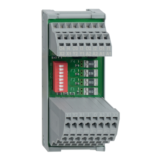
4.2 LED indicators and fuse elements . . . . . . . . . . . . . . . . . . . . . . . . . .3
4.3 Pin assignment of module connection . . . . . . . . . . . . . . . . . . . . . . .4
4.4 Pin assignment of 2 level terminal . . . . . . . . . . . . . . . . . . . . . . . . . .5
4.5 Pin assignment of 4 level terminal . . . . . . . . . . . . . . . . . . . . . . . . . .5
4.6 DIP switch configuration . . . . . . . . . . . . . . . . . . . . . . . . . . . . . . . . .5
4.7 Wiring example . . . . . . . . . . . . . . . . . . . . . . . . . . . . . . . . . . . . . . . .6
5
5.1 Functional testing. . . . . . . . . . . . . . . . . . . . . . . . . . . . . . . . . . . . . . .8
5.2 Maintenance . . . . . . . . . . . . . . . . . . . . . . . . . . . . . . . . . . . . . . . . . .8
6
6.1 Disassembly. . . . . . . . . . . . . . . . . . . . . . . . . . . . . . . . . . . . . . . . . . .8
6.2 Disposal . . . . . . . . . . . . . . . . . . . . . . . . . . . . . . . . . . . . . . . . . . . . . .8
7
7.1 Configuration examples . . . . . . . . . . . . . . . . . . . . . . . . . . . . . . . . . .8
1. About this document
1.1 Function
These operating instructions provide all the information required for
mounting, commissioning, safe operation and also disassembly of
the device. The operating instructions must be available in a legible
condition and a complete version in the vicinity of the device.
1.2 Target group: authorised qualified personnel
All operations described in this operating instructions manual must
be carried out by trained specialist personnel, authorised by the plant
operator only.
Please make sure that you have read and understood these operating
instructions and that you know all applicable legislations regarding
occupational safety and accident prevention prior to installation and
putting the component into operation.
The machine builder must carefully select the harmonised standards
to be complied with as well as other technical specifications for the
selection, mounting and integration of the components.
1.3 Explanation of the symbols used
Information, hint, note:
This symbol is used for identifying useful additional information.
Caution: Failure to comply with this warning notice could
lead to failures or malfunctions.
Warning: Failure to comply with this warning notice could
lead to physical injury and/or damage to the machine.
1.4 Appropriate use
The products described in these operating instructions are developed to
execute safety-related functions as part of an entire plant or machine. It
is the responsibility of the manufacturer of a machine or plant to ensure
the correct functionality of the entire machine or plant.
The passive distribution module may only be used in accordance
with the following versions or for the applications authorised by the
manufacturer. Detailed information regarding the range of applications
can be found in the chapter "Product description".
1.5 General safety instructions
The user must observe the safety instructions in this operating
instructions manual, the country-specific installation standards as well
as all prevailing safety regulations and accident prevention rules.
Further technical information can be found in the Schmersal
catalogues or in the online catalogue on the Internet:
www.schmersal.net.
The information contained in this operating instructions manual is
provided without liability and is subject to technical modifications.
There are no residual risks, provided that the safety instructions as well
as the instructions regarding mounting, commissioning, operation and
maintenance are observed.
EN
PDM-SD-4CC-SD
1
Advertisement
Table of Contents

Related Manuals for schmersal PDM-SD-4CC-SD


Summary of Contents for schmersal PDM-SD-4CC-SD
-
Page 1: Table Of Contents
4.3 Pin assignment of module connection ..... . .4 Further technical information can be found in the Schmersal 4.4 Pin assignment of 2 level terminal ......5 catalogues or in the online catalogue on the Internet: 4.5 Pin assignment of 4 level terminal . -
Page 2: Warning About Misuse
4 electronic safety switchgear units with SD interface Green “F4” LED: Device connection 4 fuse element manufactured by SCHMERSAL. It serves to connect up to 4 safety Green “F3” LED: Device connection 3 fuse element switchgear units in series. -
Page 3: General Mounting Instructions
Operating instructions Passive distribution module PDM-SD-4CC-SD 3. Mounting 4. Electrical connection 3.1 General mounting instructions 4.1 General information for electrical connection The distribution module is designed to be mounted in a switch cabinet. The module can be attached to a standard 35 mm rail in accordance The electrical connection may only be carried out by with EN 60715. -
Page 4: Pin Assignment Of Module Connection
Operating instructions Passive distribution module PDM-SD-4CC-SD 4.3 Pin assignment of module connection 2 level terminal Input and output signals of safety switchgear Safety signals and supply voltage POWER 4 level terminal Y1 Y2 A1 O A2 X1 X2 Safety switchgear connection 4... -
Page 5: Pin Assignment Of 2 Level Terminal
Operating instructions Passive distribution module PDM-SD-4CC-SD 4.4 Pin assignment of 2 level terminal 4.6 DIP switch configuration The position of the DIP switch is shown in black. Input and output signals of safety switchgear SD output if 4 devices are connected... -
Page 6: Wiring Example
Operating instructions Passive distribution module PDM-SD-4CC-SD 4.7 Wiring example Terminals Optional extra SD harness with distribution mo- SD-Out dules for additional safety function SD-In SD Gateway SD-Out +24 VDC 0 VDC +24 VDC Power supply 0 VDC Safety IN 1... - Page 7 Operating instructions Passive distribution module PDM-SD-4CC-SD Y2 Y1 A2 A1 I1 I2 I3 I4 O1 O2 O3 O4 A1 A2 X1 X2 Y2 Y1 A2 A1 I1 I2 I3 I4 O1 O2 O3 O4 A1 A2 X1 X2 - Module in middle...
-
Page 8: Set-Up And Maintenance
7. Configuration 7.1 Configuration examples 3 configurations are shown respectively for the different SCHMERSAL devices. One configuration with long cable lengths (maximum), one configuration with medium cable lengths (medium) and one configuration with shorter cable lengths (small). The following assumptions are made for the configuration examples listed in the table: •...
Need help?
Do you have a question about the PDM-SD-4CC-SD and is the answer not in the manual?
Questions and answers