
Related Manuals for Sunway SMG-C Series

Summary of Contents for Sunway SMG-C Series
- Page 1 Synway SMG-C Series Analog Gateway SMG1008C SMG1016C SMG1032C Analog Gateway Version 1.7.0 Synway Information Engineering Co., Ltd www.synway.net...
-
Page 2: Table Of Contents
3.5.9 Dialing Rule ......................44 3.5.10 Dialing Timeout .......................47 3.5.11 Cue Tone ........................48 3.5.12 Color Ring.......................49 3.5.13 QoS ........................50 3.5.14 Action URL......................51 Port Settings ....................51 3.6.1 FXS.........................51 3.6.2 FXO ........................56 SMG-C Series Analog Gateway User Manual (Version 1.7.0) Page i... - Page 3 Access Control......................90 3.9.13 PING Test .......................92 3.9.14 TRACERT Test .......................93 3.9.15 Change Password ....................94 3.9.16 Restart ........................94 Appendix A Technical Specifications..........95 Appendix B Troubleshooting ..............96 Appendix C Technical/sales Support ..........99 SMG-C Series Analog Gateway User Manual (Version 1.7.0) Page ii...
-
Page 4: Copyright Declaration
Moreover, Synway assumes no responsibility in obtaining permission and authorization of any third party patent, copyright or product involved in relation to the use of this document. SMG-C Series Analog Gateway User Manual (Version 1.7.0) Page iii... -
Page 5: Revision History
Synway Information Engineering Co., Ltd Revision History Version Date Comments Version 1.7.0 2017-03 Initial publication Note: Please visit our website http://www.synway.net to obtain the latest version of this document. SMG-C Series Analog Gateway User Manual (Version 1.7.0) Page iv... -
Page 6: Chapter 1 Product Introduction
Chapter 1 Product Introduction Thank you for choosing Synway SMG-C Series Analog Gateway! The Synway SMG-C series analog gateway products (hereinafter referred to as ‘SMG-C analog gateway’) are mainly used for connecting traditional phone sets, fax machines and PBXes with the IP telephony network or IP PBX. - Page 7 The gateway can register to Synway DCMS and accept the management of the Centralized Manage platform. Signaling & Protocol Description SIP Signaling Supported protocol: SIP V1.0/2.0, RFC3261. CODEC G.711A, G.711U, G.729A/B, G.723, G.722, AMR, iLBC Voice DTMF Mode RFC2833, SIP INFO, INBAND SMG-C Series Analog Gateway User Manual (Version 1.7.0) Page 2...
-
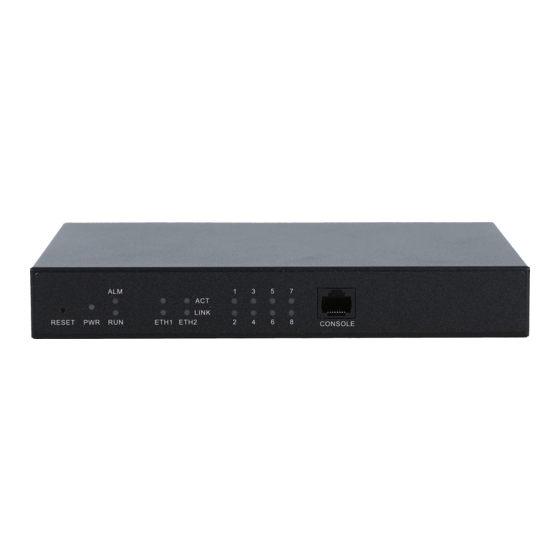
Page 8: Hardware Description
12V power supply. See below for product appearance. Alarm Indicator Power Indicator Reset Button Console Run Indicator Port LAN Indicator Channel Indicator Figure 1-2 SMG1008C Front View Grounding Stud Power RJ11 Interface SMG-C Series Analog Gateway User Manual (Version 1.7.0) Page 3... - Page 9 Maximum Transmission Distance: 1500m Charge Mode: Negative Anti-billing Supported Console Port Amount: 1 Type: RS-232 Baud Rate: 115200bps Connector: RJ45 to DB-9 Connector Data Bits: 8 bits Stop Bit: 1 bit Parity Unsupported SMG-C Series Analog Gateway User Manual (Version 1.7.0) Page 4...
-
Page 10: Alarm Info
During runtime, if the alarm indicator lights up or flashes, it indicates that the device goes abnormal. If you cannot figure out and solve the problem by yourself, please contact our technicians for help. Go to Appendix C Technical/sales Support to find the contact way. SMG-C Series Analog Gateway User Manual (Version 1.7.0) Page 5... -
Page 11: Chapter 2 Quick Guide
Step 8: Make phone calls. Note: For your easy understanding and manipulation, all examples given in this step do not involve registration, that is, SIP initiates calls in a point-to-point mode. SMG-C Series Analog Gateway User Manual (Version 1.7.0) Page 6... - Page 12 IP address which initiates the call and select the port group created in Step1 as ‘Destination Port Group’. You may use the default values of other configuration items and required not to leave ‘Description’ empty. SMG-C Series Analog Gateway User Manual (Version 1.7.0) Page 7...
- Page 13 If the dialing fails, the FXS port will send busy tones to Station. At this time Station can: Hang up to go back to the ringing state; then pick up the call again to recover the talk with Remote A. SMG-C Series Analog Gateway User Manual (Version 1.7.0) Page 8...
- Page 14 If you cannot figure out and solve the problem by yourself, please contact our technicians for help. Otherwise it may lead to a drop in performance or unexpected errors. SMG-C Series Analog Gateway User Manual (Version 1.7.0) Page 9...
-
Page 15: Chapter 3 Web Configuration
‘System Tools Change Password’ on the WEB interface. For detailed instructions, refer to 3.9.15 Change Password. After login, you can see the main interface as below. Figure 3-2 Main Interface SMG-C Series Analog Gateway User Manual (Version 1.7.0) Page 10... -
Page 16: Operation Info
The three parameters from left to right are IP address, subnet mask and default IP Address gateway of LAN. DNS Server DNS server address of LAN. Receive Packets The amount of receive packets after the gateway’s startup, including three options: SMG-C Series Analog Gateway User Manual (Version 1.7.0) Page 11... -
Page 17: Channel State
The number corresponding to the port. Voltage Line voltage on the channel, calculated by volt (V). State Displays the channel state in real time. You can move the mouse onto the channel SMG-C Series Analog Gateway User Manual (Version 1.7.0) Page 12... -
Page 18: Call Count
Total number of calls which fail because no routing rules are matched. Total number of calls which fail as the called party number does not conform to the Dialing Failure dialing rule or due to dialing timeout. SMG-C Series Analog Gateway User Manual (Version 1.7.0) Page 13... -
Page 19: Sip Message Count
SIP and FXS/FXO. The gateway can work normally after configuration. See Figure 3-9 for the Quick Config-Network Settings interface. Refer to 3.9.2 Network for detailed settings. After configuration, click Next to enter the SIP Settings interface. SMG-C Series Analog Gateway User Manual (Version 1.7.0) Page 14... - Page 20 FXS interface. Refer to 3.6.1 FXS for detailed settings. After configuration, click Back to go back to the SIP Settings interface; click Next to enter the FXO Settings interface. SMG-C Series Analog Gateway User Manual (Version 1.7.0) Page 15...
-
Page 21: Voip Settings
Media. See Figure 3-14. SIP Settings is used to configure the general SIP parameters, SIP Compatibility is used to set which SIP servers and SIP messages will the gateway be compatible SMG-C Series Analog Gateway User Manual (Version 1.7.0) Page 16... - Page 22 SIP server, NAT Setting is used to configure the parameters for NAT, and Media Settings is to set the RTP port and the payload type. Figure 3-14 VoIP Settings SMG-C Series Analog Gateway User Manual (Version 1.7.0) Page 17...
-
Page 23: Sip
Unregistered; when Register Gateway is set to Yes, the value of this item is either Failed or Registered. Register Gateway Sets whether to register the gateway as a whole. The default value is No. Only SMG-C Series Analog Gateway User Manual (Version 1.7.0) Page 18... -
Page 24: Sip Compatibility
SIP servers and SIP messages will the gateway be compatible with. After configuration, click Save to save your settings into the gateway or click Reset to restore the configurations. SMG-C Series Analog Gateway User Manual (Version 1.7.0) Page 19... - Page 25 Synway Information Engineering Co., Ltd Figure 3-16 SIP Compatibility Setting Interface SMG-C Series Analog Gateway User Manual (Version 1.7.0) Page 20...
- Page 26 Server Status status, with the default value of 0 (feature disabled), calculated by s. It is suggested Detection Cycle to set to 15s if this feature is necessary to be used. SMG-C Series Analog Gateway User Manual (Version 1.7.0) Page 21...
-
Page 27: Sip Station
The bound port to a SIP station must be an FXO port and unique. The username must be the same as that used to register the SIP terminal to the gateway. SMG-C Series Analog Gateway User Manual (Version 1.7.0) Page 22... - Page 28 Click Modify in the above figure to modify the configuration of the SIP station. See Figure 3-20. The configuration items on this interface are the same as those on the Add New SIP Station interface. SMG-C Series Analog Gateway User Manual (Version 1.7.0) Page 23...
-
Page 29: Sip Server
SIP server. See Figure 3-21 below. Figure 3-21 SIP Server Interface Click Add New to add SIP servers manually. See Figure 3-22. You can configure basic SIP server information on this interface. SMG-C Series Analog Gateway User Manual (Version 1.7.0) Page 24... - Page 30 Click Modify in the above figure to modify the configuration of the SIP server. See Figure 3-24. The configuration items on this interface are the same as those on the Add New SIP Server interface. SMG-C Series Analog Gateway User Manual (Version 1.7.0) Page 25...
-
Page 31: Nat Setting
See Figure 3-25 for the NAT setting interface where you can configure the parameters for NAT. After configuration, click Save to save your settings into the gateway or click Reset to restore the configurations. SMG-C Series Analog Gateway User Manual (Version 1.7.0) Page 26... - Page 32 Auto Nat DisableAutoNat, Enable PMP and Enable UPNP, with the default value of Auto Nat. Outer Network The address of the outer network acquired automatically once the PMP or UPNP SMG-C Series Analog Gateway User Manual (Version 1.7.0) Page 27...
- Page 33 RTP Self-adaption be updated to the actual RTP reception address or port. By default, this feature is disabled. SMG-C Series Analog Gateway User Manual (Version 1.7.0) Page 28...
-
Page 34: Media
RFC2833, In-band and Signaling, with the default value of RFC2833. Payload of the RFC2833 formatted DTMF signals on the IP channel. Range of RFC2833 Payload value: 90~127, with the default value of 101. SMG-C Series Analog Gateway User Manual (Version 1.7.0) Page 29... - Page 35 Set the minimum threshold for the energy processed by AGC. Signals below this Minimum Input threshold will not be processed by AGC. Range of value: -60~ -25, calculated by Energy dB, with the default value of -60. SMG-C Series Analog Gateway User Manual (Version 1.7.0) Page 30...
-
Page 36: Advanced Settings
IP to FXS port; QoS uses the differentiated services technology to increase the gateway’s service quality. Action URL is used to designate the server path to report the on-hook or off-hook state of the FXS channel. SMG-C Series Analog Gateway User Manual (Version 1.7.0) Page 31... -
Page 37: Fxs
See Figure 3-28 for the FXS configuration interface. The table below explains the items shown in the above figure. Item Description Sets whether to enable the hook-flash detection feature or not, with the default Hook-flash Detection setting of being disabled. SMG-C Series Analog Gateway User Manual (Version 1.7.0) Page 32... - Page 38 If a dialog box pops up after you save your settings asking you to restart the system, do it immediately to apply the changes. Refer to 3.9.16 Restart for detailed instructions. SMG-C Series Analog Gateway User Manual (Version 1.7.0) Page 33...
-
Page 39: Fxo
The maximum waiting time for the detection of the calling party number from FXO Detection Time port. Range of value: 1~20, calculated by s, with the default value of 10. SMG-C Series Analog Gateway User Manual (Version 1.7.0) Page 34... - Page 40 Sets the delay to send the CalleeID to PBX after you pick up and dial. Range of Delay after Dial value: 200~2000, calculated by ms, with the default value of 1000. SMG-C Series Analog Gateway User Manual (Version 1.7.0) Page 35...
- Page 41 If a dialog box pops up after you save your settings asking you to restart the system, do it immediately to apply the changes. Refer to 3.9.16 Restart for detailed instructions. SMG-C Series Analog Gateway User Manual (Version 1.7.0) Page 36...
-
Page 42: Tone Detector
The unique index of each group of tone detectors. Tone There are three options: Dial Tone, Busy Tone and Ringback Tone. Type There are two options: Continuous Tone and Periodic Tone. SMG-C Series Analog Gateway User Manual (Version 1.7.0) Page 37... -
Page 43: Tone Generator
200ms play and 600ms pause, then 200ms play and 1s pause. You can configure the tone generator manually. The exact explanation about the format and the meaning is described on SMG-C Series Analog Gateway User Manual (Version 1.7.0) Page 38... -
Page 44: Dtmf
DTMF Display via Once this feature is enabled, the received/sent DTMF will be displayed upon you Channels Status putting the mouse on the icon of channel status. The default value is disabled. SMG-C Series Analog Gateway User Manual (Version 1.7.0) Page 39... -
Page 45: Ringing Scheme
See Figure 3-34 for the Ringing Scheme Configuration interface. The gateway can execute different ringing schemes according to the callerID or Alert-Info.. The table below explains the items shown in the above figure. Item Description SMG-C Series Analog Gateway User Manual (Version 1.7.0) Page 40... -
Page 46: Fax
The real-time IP fax mode. The optional values are T.38, Pass-through and Disable, Fax Mode and the default value is Disable which means to disable both T.38 and Pass-through. See Figure 3-36 for the fax configuration under the T.38 mode. SMG-C Series Analog Gateway User Manual (Version 1.7.0) Page 41... - Page 47 (Redundancy Error Correction) and t38UDPFEC (Forward Mode Error Correction), with the default value of t38UDPRedundancy. If you set Fax Mode to Pass-through, you can see the interface shown as Figure 3-37. SMG-C Series Analog Gateway User Manual (Version 1.7.0) Page 42...
-
Page 48: Function Key
102. 3.5.8 Function Key See Figure 3-38 for the Function Key Configuration interface. Here you can set a cluster of combination keys to query a related number. SMG-C Series Analog Gateway User Manual (Version 1.7.0) Page 43... -
Page 49: Dialing Rule
Add New button on the bottom right corner. See Figure 3-40 for the dialing rule adding interface. SMG-C Series Analog Gateway User Manual (Version 1.7.0) Page 44... - Page 50 Only set it at the beginning of the string, representing symbol “#” “#”. There are 19 dialing rules already configured on the gateway for easy use. See below for detailed information. Priority Dialing Rule Description SMG-C Series Analog Gateway User Manual (Version 1.7.0) Page 45...
- Page 51 Click Modify in Figure 3-39 to modify the dialing rules. See Figure 3-41 for the dialing rule modification interface. The configuration items on this interface are the same as those on the Add New Dialing Rule interface. SMG-C Series Analog Gateway User Manual (Version 1.7.0) Page 46...
-
Page 52: Dialing Timeout
Figure 3-42 Dialing Rule Configuration Interface (Character) 3.5.10 Dialing Timeout Figure 3-43 Dialing Timeout Info Interface See Figure 3-43 for the dialing timeout info interface. The table below explains the items shown in the above figure. SMG-C Series Analog Gateway User Manual (Version 1.7.0) Page 47... -
Page 53: Cue Tone
See Figure 3-45 for the Cue Tone interface. The table below explains the items shown in the above figure. Item Description Upload a file of cue Uploads a user-defined cue tone file to the gateway. tone Click Save to save the above settings into the gateway. SMG-C Series Analog Gateway User Manual (Version 1.7.0) Page 48... -
Page 54: Color Ring
After configuration, click Upload to upload the color ring file to the gateway or click Return to cancel the upload. See Figure 3-48 for the Color Ring Management interface after the upload. SMG-C Series Analog Gateway User Manual (Version 1.7.0) Page 49... -
Page 55: Qos
The table below explains the items shown in the above figure. Item Description Sets whether to enable the OoS differentiated services. By default, it is disabled. SMG-C Series Analog Gateway User Manual (Version 1.7.0) Page 50... -
Page 56: Action Url
Port Settings includes three parts: FXS, FXO and Port Group. See Figure 3-52. Figure 3-52 Port Settings 3.6.1 FXS Figure 3-53 FXS Settings Interface See Figure 3-53 for the FXS settings interface. The list in the above figure shows the feature and SMG-C Series Analog Gateway User Manual (Version 1.7.0) Page 51... - Page 57 The table below explains the configuration items on the FXS modification interface. Item Description Port Serial number of the FXS port on the device. Type Type of the port on the device (FXS). This item is not configurable. SMG-C Series Analog Gateway User Manual (Version 1.7.0) Page 52...
- Page 58 The default setting is disabled. Do Not Disturb. If this feature is enabled, the FXS port will reply the 403 message to reject all incoming calls. The default setting is disabled. SMG-C Series Analog Gateway User Manual (Version 1.7.0) Page 53...
- Page 59 Or you can click Batch to modify several pieces of FXS settings at the same time. See Figure 3-55 below for the FXS batch modification interface. The configuration items on this interface are the same as those on the FXS modification interface (Figure 3-54). SMG-C Series Analog Gateway User Manual (Version 1.7.0) Page 54...
- Page 60 Synway Information Engineering Co., Ltd Figure 3-55 FXS Batch Modification Some configuration items on this interface are the same as those on the FXS Modification Interface. The others are described in the table below. SMG-C Series Analog Gateway User Manual (Version 1.7.0) Page 55...
-
Page 61: Fxo
See Figure 3-56 for the FXO Settings interface. The list in the above figure shows the feature and properties of each FXO port. Click Modify in Figure 3-56 to modify the properties of the corresponding port. See Figure 3-57 for the FXO Modification interface. SMG-C Series Analog Gateway User Manual (Version 1.7.0) Page 56... - Page 62 Registration password of the port. To register a port to the SIP server, both items Password SIP Account and Password must be filled in. SMG-C Series Analog Gateway User Manual (Version 1.7.0) Page 57...
- Page 63 After configuration, click Modify to save the settings into the gateway, click Reset to restore the configurations, or click Cancel to cancel the settings. Or you can click Batch to modify several pieces of FXO settings at the same time. See Figure SMG-C Series Analog Gateway User Manual (Version 1.7.0) Page 58...
- Page 64 The ending serial number of the FXO port on the device in the batch setting. Starting SIP Account The starting SIP account in the batch setting. Starting Display Name The starting displayname in the batch setting. SMG-C Series Analog Gateway User Manual (Version 1.7.0) Page 59...
-
Page 65: Port Group
See Figure 3-60 for the port group adding interface. Note that a port which has been occupied by one port group cannot be chosen by others. SMG-C Series Analog Gateway User Manual (Version 1.7.0) Page 60... - Page 66 Registration password of the port group. To register the port group to the SIP server, Password both configuration items SIP Account and Password should be filled in. SMG-C Series Analog Gateway User Manual (Version 1.7.0) Page 61...
- Page 67 Registration status of the port group. When Register Port Group is set to No, the Register Status value of this item is Unregistered; when Register Port Group is set to Yes, the value of this item may be Failed or Registered. SMG-C Series Analog Gateway User Manual (Version 1.7.0) Page 62...
- Page 68 All selected ports for a port group will be displayed in the Ports column in Figure 3-59. Note: When a port group contains multiple ports, the automatic call forward feature is invalid. SMG-C Series Analog Gateway User Manual (Version 1.7.0) Page 63...
-
Page 69: Route Settings
To clear all port groups at a time, click the Clear All button in Figure 3-59. 3.7 Route Settings Route Settings is used to specify the routing rules for calls on two directions: IPTel and TelIP. See Figure 3-62. SMG-C Series Analog Gateway User Manual (Version 1.7.0) Page 64... -
Page 70: Routing Parameters
The IPTel routing rule configuration has two modes: Standard and Character. Under the Standard mode, click Add New to add them manually. See Figure 3-65. You may use the default values of all the configuration items herein. SMG-C Series Analog Gateway User Manual (Version 1.7.0) Page 65... - Page 71 Route by Number interface. In such case, the configuration item Call Destination goes invalid and shows Route by Number on the routing rule configuration interface. The default setting is disabled. SMG-C Series Analog Gateway User Manual (Version 1.7.0) Page 66...
- Page 72 You can edit the routing rule list to add a new one or modify an old one. The exact meaning of each element of the rule is described on the page. Figure 3-67 IPTel Routing Rule Configuration Interface (Character) SMG-C Series Analog Gateway User Manual (Version 1.7.0) Page 67...
-
Page 73: Tel To Ip
If a call matches several routing rules, it will be processed according to the one with the highest priority. Description More information about each routing rule, with the default value of default. SMG-C Series Analog Gateway User Manual (Version 1.7.0) Page 68... - Page 74 You can edit the routing rule list to add a new one or modify an old one. The exact meaning of each element of the rule is described on the page. SMG-C Series Analog Gateway User Manual (Version 1.7.0) Page 69...
-
Page 75: Number Manipulation
Add New button on the bottom right corner of the list in the above figure. See Figure 3-74 for the IPTel CallerID manipulation rule adding interface. You may use the default values of all the configuration items herein. SMG-C Series Analog Gateway User Manual (Version 1.7.0) Page 70... - Page 76 More information about each number manipulation rule, with the default value of Description default. IP address from where the call is initiated. This item can be set to a specific IP Call Initiator address or “*” which indicates any IP address. SMG-C Series Analog Gateway User Manual (Version 1.7.0) Page 71...
- Page 77 CallerID manipulation rule modification interface. The configuration items on this interface are the same as those on the Add IP Tel CallerID Manipulation Rule interface. Note that the item Index cannot be modified. SMG-C Series Analog Gateway User Manual (Version 1.7.0) Page 72...
- Page 78 The exact meaning of each element of the rule is described on the page. SMG-C Series Analog Gateway User Manual (Version 1.7.0) Page 73...
-
Page 79: Ip To Tel Calleeid
IPTel CalleeID manipulation interface. The configuration items on this interface are the same as those on IP Tel CallerID Manipulation Interface (Figure 3-73). Figure 3-77 IPTel CalleeID Manipulation Interface(Standard) SMG-C Series Analog Gateway User Manual (Version 1.7.0) Page 74... -
Page 80: Tel To Ip Callerid
Description The unique index of each number manipulation rule, which denotes its priority. A Index number manipulation rule with a smaller index value has a higher priority. If a call SMG-C Series Analog Gateway User Manual (Version 1.7.0) Page 75... - Page 81 CallerID manipulation rule modification interface. The configuration items on this interface are the same as those on the Add Tel IP CallerID Manipulation Rule interface. Note that the item Index cannot be modified. SMG-C Series Analog Gateway User Manual (Version 1.7.0) Page 76...
- Page 82 The exact meaning of each element of the rule is described on the page. SMG-C Series Analog Gateway User Manual (Version 1.7.0) Page 77...
-
Page 83: Tel To Ip Calleeid
Figure 3-84 for the TelIP CalleeID manipulation interface. The configuration items on this interface are the same as those on Tel IP CallerID Manipulation Interface (Figure 3-79). Figure 3-83 TelIP CalleeID Manipulation Interface (Standard) SMG-C Series Analog Gateway User Manual (Version 1.7.0) Page 78... -
Page 84: System Tools
3.9 System Tools System Tools is mainly for gateway maintenance. It provides such features as IP modification, data backup and connectivity check. See Figure 3-85 for details. Figure 3-85 System Tools SMG-C Series Analog Gateway User Manual (Version 1.7.0) Page 79... -
Page 85: Management
Sets whether to enable the feature of sending CDR. It is required to fill in Server Send CDR Address and Server Port in case Send CDR is enabled. By default, Send CDR is disabled. SMG-C Series Analog Gateway User Manual (Version 1.7.0) Page 80... -
Page 86: Network
After configuration, click Save to save the above settings into the gateway or click Reset to restore the configurations. After changing the IP address, you shall log in the gateway again using your new IP address. SMG-C Series Analog Gateway User Manual (Version 1.7.0) Page 81... -
Page 87: Upgrade
MD5 verification before upgrading and will not start to upgrade until it passes the verification.) via Browse… and click Update. Then the file uploading interface will appear. See Figure 3-89. SMG-C Series Analog Gateway User Manual (Version 1.7.0) Page 82... - Page 88 After a successful uploading of the file, the gateway will start to upgrade the system. See Figure 3-90 and you can learn the detailed upgrading information from the upgrade information box at the bottom. SMG-C Series Analog Gateway User Manual (Version 1.7.0) Page 83...
-
Page 89: Signaling Capture
Note: Please contact our technicians if you need to downgrade the gateway to an old version. An improper operation may cause unexpected problems. 3.9.4 Signaling Capture Figure 3-91 Signaling Capture Interface SMG-C Series Analog Gateway User Manual (Version 1.7.0) Page 84... -
Page 90: Data Recording
Click Start to start the corresponding recording. Click Stop to stop the recording and download the recorded file. 3.9.6 Call Log Figure 3-93 Call Log Interface SMG-C Series Analog Gateway User Manual (Version 1.7.0) Page 85... -
Page 91: Operation Log
IP channels, and Call from Port displays the call log information generated on the port you select. All the SIP related information will be displayed in SIP Log. 3.9.7 Operation Log Figure 3-95 Operation Log Interface SMG-C Series Analog Gateway User Manual (Version 1.7.0) Page 86... -
Page 92: Backup & Upload
‘System is rebooting, please do not leave this page’ appears. See Figure 3-98. The gateway will overwrite the current configurations with the uploaded data after restart. Click Cancel to cancel this upload directly. SMG-C Series Analog Gateway User Manual (Version 1.7.0) Page 87... -
Page 93: Factory Reset
Figure 3-99 Factory Reset Interface See Figure 3-99 for the factory reset interface. Click Reset to restore all configurations on the gateway to factory settings. 3.9.10 System Monitor Figure 3-100 System Monitor Configuration Interface SMG-C Series Analog Gateway User Manual (Version 1.7.0) Page 88... -
Page 94: Centralized Manage
Note: To configure the domain name, the DNS should be already configured and the corresponding domain name must be analyzable. The name used to register the gateway to Synway DCMS, valid only when DCMS is Company Name selected. SMG-C Series Analog Gateway User Manual (Version 1.7.0) Page 89... -
Page 95: Access Control
Authenticated and encrypted. 3.9.12 Access Control Figure 3-102 Access Control List Interface See Figure 3-102 for the Access Control List interface. Once you add a piece of command to ACL, SMG-C Series Analog Gateway User Manual (Version 1.7.0) Page 90... - Page 96 However, in case the gateway restarts or the configuration is leading-in, the command will get valid automatically without the need for you to click the Apply button. SMG-C Series Analog Gateway User Manual (Version 1.7.0) Page 91...
-
Page 97: Ping Test
The information returned during the Ping test, helping you to learn the network Info connection status between the gateway and the destination address. After configuration, click Start to execute the Ping test; click End to terminate it immediately. SMG-C Series Analog Gateway User Manual (Version 1.7.0) Page 92... -
Page 98: Tracert Test
The information returned during the Tracert test, helping you to learn the detailed Info information about the jumps between the gateway and the destination address. After configuration, click Start to execute the Tracert test; click End to terminate it immediately. SMG-C Series Analog Gateway User Manual (Version 1.7.0) Page 93... -
Page 99: Change Password
See Figure 3-108 for the Restart interface. Click Restart to restart the whole gateway system. A dump file will be generated each time you restart the system. Click Download and you can download it to help troubleshoot issues. SMG-C Series Analog Gateway User Manual (Version 1.7.0) Page 94... -
Page 100: Appendix A Technical Specifications
64 kbps Type: RJ11 4.75 kbps Maximum transmission distance: 5000m iLBC 13.3/15.2 kbps Impedance Sampling Rate Telephone line impedance: Compliant with the national standard impedance for three-component 8kHz network Console Port SMG-C Series Analog Gateway User Manual (Version 1.7.0) Page 95... -
Page 101: Appendix B Troubleshooting
Q4. In what cases can I conclude that the SMG-C gateway is abnormal and turn to Synway’s technicians for help? During runtime, the run indicator does not flash or the alarm indicator lights up or flashes, SMG-C Series Analog Gateway User Manual (Version 1.7.0) Page 96... - Page 102 The feature Communication without Network is implemented via the WEB management over the analog gateway. It will automatically route a call to the FXO port in case of network failure or call timeout. SMG-C Series Analog Gateway User Manual (Version 1.7.0) Page 97...
- Page 103 Synway Information Engineering Co., Ltd Refer to in this chapter for detailed information. SMG-C Series Analog Gateway User Manual (Version 1.7.0) Page 98...
-
Page 104: Appendix C Technical/Sales Support
Wechat QR Code: Scan the QR code below to add us on Wechat. Technical Support Tel: +86-571-88864579 Mobile: +86-18905817070 Email: techsupport@sanhuid.com Email: techsupport@synway.net MSN: synway.support@hotmail.com Sales Department Tel: +86-571-88860561 Tel: +86-571-88864579 Fax: +86-571-88850923 Email: sales@synway.net SMG-C Series Analog Gateway User Manual (Version 1.7.0) Page 99...
Need help?
Do you have a question about the SMG-C Series and is the answer not in the manual?
Questions and answers