
Subscribe to Our Youtube Channel
Related Manuals for Texas Instruments LMK05318EVM


Summary of Contents for Texas Instruments LMK05318EVM
- Page 1 LMK05318EVM User's Guide Literature Number: SNAU236A June 2018 – Revised December 2018...
-
Page 2: Table Of Contents
EVM Bill of Materials ........................Appendix A Software ..................Software Installation (One-Time) ..................TICS Pro Usage for LMK05318 .......................... Revision History Table of Contents SNAU236A – June 2018 – Revised December 2018 Submit Documentation Feedback Copyright © 2018, Texas Instruments Incorporated... - Page 3 List of Figures ............LMK05318EVM With Default Jumper and DIP Switch Settings ..................Key Components - EVM Top Side ................... Key Components - EVM Bottom Side ..................Default Power Jumper Configuration ..........XO Input Interface (1 of 2) - 48.0048-MHz Oscillator and SMA Ports ..............
- Page 4 Logic Pin Descriptions - EEPROM + SPI Mode (HW_SW_CTRL = Float) ............ Logic Pin Descriptions - ROM + I C Mode (HW_SW_CTRL = 1) ......................Bill of Materials List of Tables SNAU236A – June 2018 – Revised December 2018 Submit Documentation Feedback Copyright © 2018, Texas Instruments Incorporated...
-
Page 5: Preface
Introduction Overview The LMK05318EVM is an evaluation module for the LMK05318 Network Clock Generator and Synchronizer. The EVM can be used for device evaluation, compliance testing, and system prototyping. The LMK05318 integrates two Analog PLLs (APLL) and one Digital PLL (DPLL) with programmable loop bandwidth. -
Page 6: Lmk05318Evm With Default Jumper And Dip Switch Settings
What is Needed www.ti.com Figure 1. LMK05318EVM With Default Jumper and DIP Switch Settings Introduction SNAU236A – June 2018 – Revised December 2018 Submit Documentation Feedback Copyright © 2018, Texas Instruments Incorporated... -
Page 7: Evm Quick Start
XO (Y1). 5. Connect an external 25-MHz single-ended clock input to either the PRIREF or SECREF SMA port to SNAU236A – June 2018 – Revised December 2018 LMK05318EVM User's Guide Submit Documentation Feedback Copyright © 2018, Texas Instruments Incorporated... -
Page 8: Device Revision Identification
PRIREF and SECREF: DC-coupled from SMA ports – Clock Outputs: • OUT[0:6]: AC-coupled to SMA ports • OUT7: DC-coupled to SMA ports LMK05318EVM User's Guide SNAU236A – June 2018 – Revised December 2018 Submit Documentation Feedback Copyright © 2018, Texas Instruments Incorporated... -
Page 9: Default Configuration - Eeprom Start-Up Modes
DPLL Holdover Active (active high) Clock input frequency thresholds (ppm) are relative to the frequency accuracy of the XO input. SNAU236A – June 2018 – Revised December 2018 LMK05318EVM User's Guide Submit Documentation Feedback Copyright © 2018, Texas Instruments Incorporated... -
Page 10: Device Under Test
A host device is able to program the registers (and EEPROM, if needed) with a new configuration after power-up through I C or SPI. SPI is not supported by ROM mode. LMK05318EVM User's Guide SNAU236A – June 2018 – Revised December 2018 Submit Documentation Feedback Copyright © 2018, Texas Instruments Incorporated... -
Page 11: Evm Configuration
Status LEDs for DUT STATUS[0:1] pins JP20 Jumpers Header for I C/SPI interface (MCU to DUT) USB Port for MCU SNAU236A – June 2018 – Revised December 2018 LMK05318EVM User's Guide Submit Documentation Feedback Copyright © 2018, Texas Instruments Incorporated... -
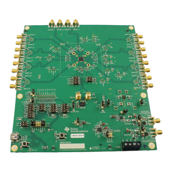
Page 12: Key Components - Evm Top Side
OUT1_P OUT6_P OUT2_P OUT5_P OUT2_N OUT5_N OUT3_N OUT4_P OUT3_P OUT4_N VIN1 VIN2 Figure 2. Key Components - EVM Top Side LMK05318EVM User's Guide SNAU236A – June 2018 – Revised December 2018 Submit Documentation Feedback Copyright © 2018, Texas Instruments Incorporated... -
Page 13: Power Supply
J1 is the main power terminal to the external power supply. Power SMA port VIN1 (J2) provides an alternative connector style to apply power through coax cable. SNAU236A – June 2018 – Revised December 2018 LMK05318EVM User's Guide Submit Documentation Feedback Copyright © 2018, Texas Instruments Incorporated... -
Page 14: Default Power Jumper Configuration
The SMA ports J2 or J3 can be used to power VIN1 or VIN2, respectively, through a coaxial cable instead of using power cables to J1. LMK05318EVM User's Guide SNAU236A – June 2018 – Revised December 2018 Submit Documentation Feedback Copyright © 2018, Texas Instruments Incorporated... -
Page 15: Logic Inputs And Outputs
Table 11 (Tie pins 1-2) Logic pins not listed in Table 10 Table 11 are the same as described in Table SNAU236A – June 2018 – Revised December 2018 LMK05318EVM User's Guide Submit Documentation Feedback Copyright © 2018, Texas Instruments Incorporated... -
Page 16: Logic Pin Descriptions - Eeprom + I
FINC STATE S7 (0=OFF, 1=ON) DPLL DCO NUMERATOR No update S7[1:3] = X1X (MCU driven) 1 (Pulsed by MCU pin) Incremented LMK05318EVM User's Guide SNAU236A – June 2018 – Revised December 2018 Submit Documentation Feedback Copyright © 2018, Texas Instruments Incorporated... -
Page 17: Logic Pin Descriptions - Eeprom + Spi Mode (Hw_Sw_Ctrl = Float)
When HW_SW_CTRL = Float, STATUS[1:0] pins must not be pulled high or low externally during POR to ensure proper start-up into EEPROM+SPI Mode. SNAU236A – June 2018 – Revised December 2018 LMK05318EVM User's Guide Submit Documentation Feedback Copyright © 2018, Texas Instruments Incorporated... -
Page 18: Xo Input
0.1-µF capacitors on C81 and C82 and opening C80, C137, and C138. Y1 and U10 should be powered down when using the external XO input path. LMK05318EVM User's Guide SNAU236A – June 2018 – Revised December 2018 Submit Documentation Feedback Copyright © 2018, Texas Instruments Incorporated... -
Page 19: Xo Input Interface (1 Of 2) - 48.0048-Mhz Oscillator And Sma Ports
C80 and C81, and C138 shares a pad with C82). U10 can be powered by a clean 3.3-V supply from LDO3 by tying JP21 pins 1-2. SNAU236A – June 2018 – Revised December 2018 LMK05318EVM User's Guide Submit Documentation Feedback Copyright © 2018, Texas Instruments Incorporated... -
Page 20: Reference Clock Inputs
Figure 7. Clock Input Interface - PRIREF (Similar for SECREF) Clock Outputs The LMK05318 has eight clock output pairs (OUT[0:7]_P/N) that can be sourced from either APLL domain. LMK05318EVM User's Guide SNAU236A – June 2018 – Revised December 2018 Submit Documentation Feedback Copyright © 2018, Texas Instruments Incorporated... -
Page 21: Status Outputs And Leds
STATUS0 and STATUS1 outputs drive orange LEDs D7 and D8 for visual indication. Each LED will turn ON when the status output is 1 (active high). SNAU236A – June 2018 – Revised December 2018 LMK05318EVM User's Guide Submit Documentation Feedback Copyright © 2018, Texas Instruments Incorporated... -
Page 22: Evm Schematics
EVM Schematics www.ti.com EVM Schematics Figure 9. Schematic 1 - Power Supplies LMK05318EVM User's Guide SNAU236A – June 2018 – Revised December 2018 Submit Documentation Feedback Copyright © 2018, Texas Instruments Incorporated... -
Page 23: Schematic 2 - Power Distribution
EVM Schematics www.ti.com Figure 10. Schematic 2 - Power Distribution SNAU236A – June 2018 – Revised December 2018 LMK05318EVM User's Guide Submit Documentation Feedback Copyright © 2018, Texas Instruments Incorporated... -
Page 24: Schematic 3 - Dc-Dc Regulator
EVM Schematics www.ti.com Figure 11. Schematic 3 - DC-DC Regulator LMK05318EVM User's Guide SNAU236A – June 2018 – Revised December 2018 Submit Documentation Feedback Copyright © 2018, Texas Instruments Incorporated... -
Page 25: Schematic 4 - Lmk05318 And Xo Input Interfaces
EVM Schematics www.ti.com Figure 12. Schematic 4 - LMK05318 and XO Input Interfaces SNAU236A – June 2018 – Revised December 2018 LMK05318EVM User's Guide Submit Documentation Feedback Copyright © 2018, Texas Instruments Incorporated... -
Page 26: Schematic 5 - Clock Input Interfaces
EVM Schematics www.ti.com Figure 13. Schematic 5 - Clock Input Interfaces LMK05318EVM User's Guide SNAU236A – June 2018 – Revised December 2018 Submit Documentation Feedback Copyright © 2018, Texas Instruments Incorporated... -
Page 27: Schematic 6 - Clock Output Interfaces (Out0 To Out3)
EVM Schematics www.ti.com Figure 14. Schematic 6 - Clock Output Interfaces (OUT0 to OUT3) SNAU236A – June 2018 – Revised December 2018 LMK05318EVM User's Guide Submit Documentation Feedback Copyright © 2018, Texas Instruments Incorporated... -
Page 28: Schematic 7 - Clock Outputs (Out4 To Out7)
EVM Schematics www.ti.com Figure 15. Schematic 7 - Clock Outputs (OUT4 to OUT7) LMK05318EVM User's Guide SNAU236A – June 2018 – Revised December 2018 Submit Documentation Feedback Copyright © 2018, Texas Instruments Incorporated... -
Page 29: Schematic 8 - Logic I/O Interfaces
EVM Schematics www.ti.com Figure 16. Schematic 8 - Logic I/O Interfaces SNAU236A – June 2018 – Revised December 2018 LMK05318EVM User's Guide Submit Documentation Feedback Copyright © 2018, Texas Instruments Incorporated... -
Page 30: Schematic 9 - Usb Mcu And I C/Spi Jumper Block
EVM Schematics www.ti.com Figure 17. Schematic 9 - USB MCU and I C/SPI Jumper Block LMK05318EVM User's Guide SNAU236A – June 2018 – Revised December 2018 Submit Documentation Feedback Copyright © 2018, Texas Instruments Incorporated... -
Page 31: Schematic 10 - Lmk61E2 Oscillator
EVM Schematics www.ti.com Figure 18. Schematic 10 - LMK61E2 Oscillator SNAU236A – June 2018 – Revised December 2018 LMK05318EVM User's Guide Submit Documentation Feedback Copyright © 2018, Texas Instruments Incorporated... -
Page 32: Schematic 11 - Dut Test Socket
EVM Schematics www.ti.com Figure 19. Schematic 11 - DUT Test Socket LMK05318EVM User's Guide SNAU236A – June 2018 – Revised December 2018 Submit Documentation Feedback Copyright © 2018, Texas Instruments Incorporated... -
Page 33: Evm Layouts
EVM Layouts www.ti.com EVM Layouts Figure 20. Top Composite View SNAU236A – June 2018 – Revised December 2018 LMK05318EVM User's Guide Submit Documentation Feedback Copyright © 2018, Texas Instruments Incorporated... -
Page 34: Top Solder Mask
EVM Layouts www.ti.com Figure 21. Top Solder Mask LMK05318EVM User's Guide SNAU236A – June 2018 – Revised December 2018 Submit Documentation Feedback Copyright © 2018, Texas Instruments Incorporated... -
Page 35: Layer 1 (Top Side) - Clock I/Os, Logic, And Power Routing, Ground Fill
EVM Layouts www.ti.com Figure 22. Layer 1 (Top Side) - Clock I/Os, Logic, and Power Routing, Ground Fill SNAU236A – June 2018 – Revised December 2018 LMK05318EVM User's Guide Submit Documentation Feedback Copyright © 2018, Texas Instruments Incorporated... -
Page 36: Layer 2 - Ground Plane
EVM Layouts www.ti.com Figure 23. Layer 2 - Ground Plane LMK05318EVM User's Guide SNAU236A – June 2018 – Revised December 2018 Submit Documentation Feedback Copyright © 2018, Texas Instruments Incorporated... -
Page 37: Layer 3 - Logic Routing, Ground Fill
EVM Layouts www.ti.com Figure 24. Layer 3 - Logic Routing, Ground Fill SNAU236A – June 2018 – Revised December 2018 LMK05318EVM User's Guide Submit Documentation Feedback Copyright © 2018, Texas Instruments Incorporated... -
Page 38: Layer 4 - Power Routing, Ground Fill
EVM Layouts www.ti.com Figure 25. Layer 4 - Power Routing, Ground Fill LMK05318EVM User's Guide SNAU236A – June 2018 – Revised December 2018 Submit Documentation Feedback Copyright © 2018, Texas Instruments Incorporated... -
Page 39: Layer 5 - Power And Ground Planes
EVM Layouts www.ti.com Figure 26. Layer 5 - Power and Ground Planes SNAU236A – June 2018 – Revised December 2018 LMK05318EVM User's Guide Submit Documentation Feedback Copyright © 2018, Texas Instruments Incorporated... -
Page 40: Layer 6 - Logic Routing, Ground Fill
EVM Layouts www.ti.com Figure 27. Layer 6 - Logic Routing, Ground Fill LMK05318EVM User's Guide SNAU236A – June 2018 – Revised December 2018 Submit Documentation Feedback Copyright © 2018, Texas Instruments Incorporated... -
Page 41: Layer 7 - Ground Plane
EVM Layouts www.ti.com Figure 28. Layer 7 - Ground Plane SNAU236A – June 2018 – Revised December 2018 LMK05318EVM User's Guide Submit Documentation Feedback Copyright © 2018, Texas Instruments Incorporated... -
Page 42: Layer 8 (Bottom Side, View From Top) - Logic And Power Routing, Ground Fill
EVM Layouts www.ti.com Figure 29. Layer 8 (Bottom Side, View From Top) - Logic and Power Routing, Ground Fill LMK05318EVM User's Guide SNAU236A – June 2018 – Revised December 2018 Submit Documentation Feedback Copyright © 2018, Texas Instruments Incorporated... -
Page 43: Bottom Solder Mask
EVM Layouts www.ti.com Figure 30. Bottom Solder Mask SNAU236A – June 2018 – Revised December 2018 LMK05318EVM User's Guide Submit Documentation Feedback Copyright © 2018, Texas Instruments Incorporated... -
Page 44: Bottom Composite View
EVM Layouts www.ti.com Figure 31. Bottom Composite View LMK05318EVM User's Guide SNAU236A – June 2018 – Revised December 2018 Submit Documentation Feedback Copyright © 2018, Texas Instruments Incorporated... -
Page 45: Evm Bill Of Materials
CAP, CERM, 10 uF, 10 V, +/- 10%, 10uF LMK212BJ106KG-T Taiyo Yuden X5R, 0805 CAP, CERM, 0.1 uF, 25 V, +/- 5%, 0.1uF C0603C104J3RACTU Kemet X7R, 0603S SNAU236A – June 2018 – Revised December 2018 LMK05318EVM User's Guide Submit Documentation Feedback Copyright © 2018, Texas Instruments Incorporated... - Page 46 Diode, Zener, 7.5 V, 550 mW, SMB 1SMB5922BT3G ON Semiconductor Diode, Schottky, 30 V, 0.2 A, SOT-23 BAT54-7-F Diodes Inc. LED, Red, SMD LTST-C170KRKT Lite-On LMK05318EVM User's Guide SNAU236A – June 2018 – Revised December 2018 Submit Documentation Feedback Copyright © 2018, Texas Instruments Incorporated...
- Page 47 RES, 1.50 k, 1%, 0.1 W, AEC-Q200 1.50k CRCW06031K50FKEA Vishay-Dale Grade 0, 0603 RES, 2.43 k, 1%, 0.1 W, AEC-Q200 2.43k CRCW06032K43FKEA Vishay-Dale Grade 0, 0603 SNAU236A – June 2018 – Revised December 2018 LMK05318EVM User's Guide Submit Documentation Feedback Copyright © 2018, Texas Instruments Incorporated...
- Page 48 Switch, Tactile, SPST-NO, 0.05A, S4, S8 FSM4JSMA TE Connectivity 12V, SMT S5, S6, S7 Switch, Slide, SPST 3 poles, SMT 219-3LPST Electrocomponents LMK05318EVM User's Guide SNAU236A – June 2018 – Revised December 2018 Submit Documentation Feedback Copyright © 2018, Texas Instruments Incorporated...
- Page 49 C138 X7R, 0603 C106, C107, CAP, CERM, 100 pF, 50 V, +/- 5%, C111, C112, 100pF 06035A101JAT2A C0G/NP0, 0603 C113 SNAU236A – June 2018 – Revised December 2018 LMK05318EVM User's Guide Submit Documentation Feedback Copyright © 2018, Texas Instruments Incorporated...
- Page 50 TP33 TP19, TP20, Test Point, Miniature, Black, TH 5001 Keystone TP21, TP22 Socket, QFN-48, 0.5 mm, SMT 106458-0020 HSIO Technologies LMK05318EVM User's Guide SNAU236A – June 2018 – Revised December 2018 Submit Documentation Feedback Copyright © 2018, Texas Instruments Incorporated...
-
Page 51: Appendix A Software
When the desired device functionality and performance has been confirmed, the active configuration can be programmed to the EEPROM to allow auto-startup on the next power cycle. SNAU236A – June 2018 – Revised December 2018 Software Submit Documentation Feedback Copyright © 2018, Texas Instruments Incorporated... - Page 52 Removed steps in the Software Installation (One-Time) instructions ........... • Added information to the TICS Pro Usage for LMK05318 set of instructions Revision History SNAU236A – June 2018 – Revised December 2018 Submit Documentation Feedback Copyright © 2018, Texas Instruments Incorporated...
- Page 53 STANDARD TERMS FOR EVALUATION MODULES Delivery: TI delivers TI evaluation boards, kits, or modules, including any accompanying demonstration software, components, and/or documentation which may be provided together or separately (collectively, an “EVM” or “EVMs”) to the User (“User”) in accordance with the terms set forth herein.
- Page 54 FCC Interference Statement for Class B EVM devices NOTE: This equipment has been tested and found to comply with the limits for a Class B digital device, pursuant to part 15 of the FCC Rules. These limits are designed to provide reasonable protection against harmful interference in a residential installation.
- Page 55 【無線電波を送信する製品の開発キットをお使いになる際の注意事項】 開発キットの中には技術基準適合証明を受けて いないものがあります。 技術適合証明を受けていないもののご使用に際しては、電波法遵守のため、以下のいずれかの 措置を取っていただく必要がありますのでご注意ください。 1. 電波法施行規則第6条第1項第1号に基づく平成18年3月28日総務省告示第173号で定められた電波暗室等の試験設備でご使用 いただく。 2. 実験局の免許を取得後ご使用いただく。 3. 技術基準適合証明を取得後ご使用いただく。 なお、本製品は、上記の「ご使用にあたっての注意」を譲渡先、移転先に通知しない限り、譲渡、移転できないものとします。 上記を遵守頂けない場合は、電波法の罰則が適用される可能性があることをご留意ください。 日本テキサス・イ ンスツルメンツ株式会社 東京都新宿区西新宿6丁目24番1号 西新宿三井ビル 3.3.3 Notice for EVMs for Power Line Communication: Please see http://www.tij.co.jp/lsds/ti_ja/general/eStore/notice_02.page 電力線搬送波通信についての開発キットをお使いになる際の注意事項については、次のところをご覧ください。http:/ /www.tij.co.jp/lsds/ti_ja/general/eStore/notice_02.page 3.4 European Union 3.4.1 For EVMs subject to EU Directive 2014/30/EU (Electromagnetic Compatibility Directive): This is a class A product intended for use in environments other than domestic environments that are connected to a low-voltage power-supply network that supplies buildings used for domestic purposes.
- Page 56 Notwithstanding the foregoing, any judgment may be enforced in any United States or foreign court, and TI may seek injunctive relief in any United States or foreign court. Mailing Address: Texas Instruments, Post Office Box 655303, Dallas, Texas 75265 Copyright © 2018, Texas Instruments Incorporated...
- Page 57 TI products. TI’s provision of these resources does not expand or otherwise alter TI’s applicable warranties or warranty disclaimers for TI products. Mailing Address: Texas Instruments, Post Office Box 655303, Dallas, Texas 75265 Copyright © 2018, Texas Instruments Incorporated...
Need help?
Do you have a question about the LMK05318EVM and is the answer not in the manual?
Questions and answers