
Related Manuals for Stanley SXAC2550222


Summary of Contents for Stanley SXAC2550222
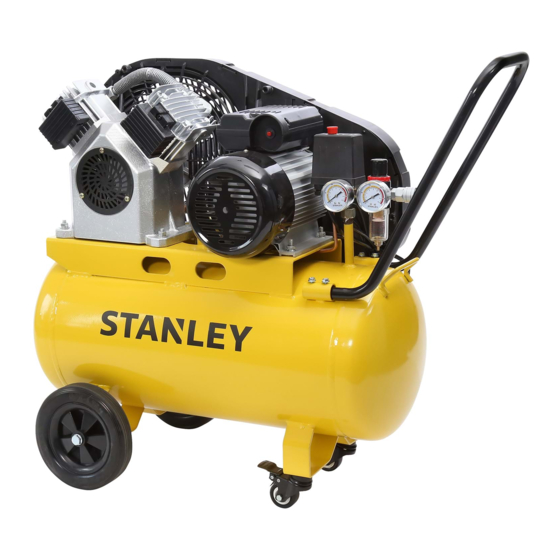
- Page 1 AIR COMPRESSOR BELT DRIVE 2.5HP 50L For service, spare parts or product information, MODEL NO. please contact Smart Marketing Group Pty. Ltd. SXAC2550222 AUST. 1300 660 457 N.Z. 0800 474 876...
- Page 2 SUGGESTED APPLICATIONS CONTENTS You may use most air tools with this compressor. Section Page Some examples of tools are: Contents INFLATION FASTENING Suggested Applications • Car and bike tires • Framing gun • Sports toys • C-bradder Introduction • Pool toys •...
- Page 3 INTRODUCTION What is covered. • Manufacturing fault or defect. Dear Customer, How to claim under this warranty. Thank you for purchasing this compressor which has • Call customer service. passed through our extensive quality assurance processes. Every care has been taken to ensure that it reaches you •...
- Page 4 COMPLETE WARRANTY STATEMENT – COMPRESSOR As soon as you have purchased the compressor, we Damage caused by third party accessories is not covered recommend that you check to make sure it is intact and under this warranty. that you read the operating instructions carefully before Damage caused to attached equipment or third party using it.
- Page 5 LUBRICATION OF COMPRESSOR WORK ENVIRONMENT This compressor is OIL FREE. Therefore there Do not expose your air compressor to rain or use in damp is NO oil used for lubrication. or wet conditions. Keep the work area well lit. Always ensure your compressor is level and stable.
- Page 6 DO NOT ABUSE DISCONNECT AIR COMPRESSOR THE POWER CORD Ensure that the air compressor is disconnected from the mains supply when not in use, before servicing, cleaning, Never yank or pull on the power cord to disconnect it making adjustments or when changing any accessories. from the mains supply socket.
- Page 7 CHECK DAMAGED PARTS PERSONAL SAFETY Before using the air compressor it should be carefully Clothing checked to determine that it will operate properly and Do not wear loose clothing, jewellery or anything that perform its intended function. could get caught in moving machinery. Check for the correct alignment of moving parts ensuring Hair that they do not bind.
- Page 8 IMPORTANT ELECTRICAL DATA This air compressor is fitted with a sealed electrical connection plug that is compatible with the mains power supply for Australia / New Zealand and meets the requirements of international standards. This air compressor must be connected to a supply voltage that is equal to that stated on the rating label. If the mains power connection plug or power cord becomes damaged it must be replaced with a complete assembly that is identical to the original, and this must be replaced by an authorised service centre.
- Page 9 13 12 COMPONENTS AND CONTROLS 1. Belt guard 2. Tank 3. Wheels 4. Tank drain tap 5. Lockable caster wheels 6. Safety Valve (not shown) 7. Tank pressure gauge 8. Front handle 9. Pressure switch 10. On / Off button – red colour 11.
- Page 10 OPERATING INSTRUCTIONS Unpacking Carefully unpack your air compressor. This air compressor is bulky and heavy, two (2) person lift required. Dispose of all packing material in an environmentally responsible manner. Assembly Your air compressor requires minor assembly before initial operation. Check that you have all required components required for assembly and initial use.
- Page 11 HANDLE PIC. 3 1. Loosen bolts in tubes welded to the tank. Slide handle 2. Push handle into tubes welded on the tank. into tubes 3. Tighten the bolts to hold handle in place, Pic. 3. Tighten bolts to hold handle AIR FILTER PIC.
- Page 12 USING THE AIR COMPRESSOR MOTOR RESET Your compressor does not require running in. Before use Your air compressor is fitted with a motor reset button, ensure you have read and understood these instructions. Pic. 6. If your air compressor has failed to start, or stopped suddenly, there is high likelihood that the motor reset Before use ensure this compressor is fully assembled as per button has been activated.
- Page 13 PIC. 7 Not supplied, purchased separately. FILTER REGULATOR The configuration of tools and accessories can be varied to suit your particular requirements. A basic recommended set Pic. 8 up is shown in Pic. 7. This air compressor comes with a filter regulator, which will When you have finished using your air compressor filter some water and other particulates from the air as it follow these simple steps;...
- Page 14 ADJUSTING THE PRESSURE PIC. 9 Regulator To adjust the outlet air pressure, use the red coloured regulator knob and check the pressure on the outlet pressure gauge, Pic. 9. If the pressure needs to be lower, turn anti clockwise. If the pressure needs to be higher, turn clockwise. Use the gauge to ensure you set the correct working pressure.
- Page 15 AIR FITTING PIC. 11 Pic. 11 Tank Outlet This air compressor is fitted with a ‘Nitto style’ pressure pressure gauge gauge (female) socket. 1. Push in the ‘Nitto style’ male plug (not included). 2. Fully and completely push the ‘Nitto style’ male plug (not included) into the ‘Nitto style’...
- Page 16 BELT TENSION PIC. 13 Pic. 13 Correct belt tension is paramount to a safe and reliable 10 - 15mm air compressor. Too tight a belt can cause damage to bearings and premature motor failure. These failures will not be covered by warranty. Too loose a belt can cause poor performance and excess heat due to slippage which can also lead to premature component failure.
- Page 17 BELT REPLACEMENT PIC. 15 Loosen and remove Pic. 15 these screws. The belt will need replacing if it has been damaged, worn, or it has reached 250 hours of use. To replace the belt follow these steps; 1. Undo and remove the belt guard screws, see Pic. 15. 2.
- Page 18 MAINTENANCE Daily: Before use 1. Seal the tank drain tap,see page 15, Pic. 12. 2. Check safety valve operation,see page 14, Pic. 10. 3. Check the belt tension, Pic 13. Page 16. Movement should be 10-15mm. Adjust if required. Page 16. 4.
- Page 19 PARTS DIAGRAM Part Description SMG Part No. Part Description SMG Part No. Pump Tube Set 95 STVTPT Handle 95 STDDH Air Filter 95 STOFV2AF Filter Regulator 95 STREGWT Exhaust Elbow 95 BRC185EE Pressure Gauge Outlet 95 STOPG Exhaust Tube Set 95 STBDET Outlet Nitto Style Socket (Female) 95 STNSF...
- Page 20 STANLEY®, The STANLEY Logo, The Notched Rectangle and the Yellow and Black Diagonal Package Design are all trademarks of the Stanley Black & Decker, Inc or an affiliate thereof and are used under license. Product manufactured and distributed by Smart Marketing Group Pty Ltd.
Need help?
Do you have a question about the SXAC2550222 and is the answer not in the manual?
Questions and answers