Table of Contents
Advertisement
Quick Links
Advertisement
Table of Contents

Related Manuals for Tridonic LLE G2 PRE


Summary of Contents for Tridonic LLE G2 PRE
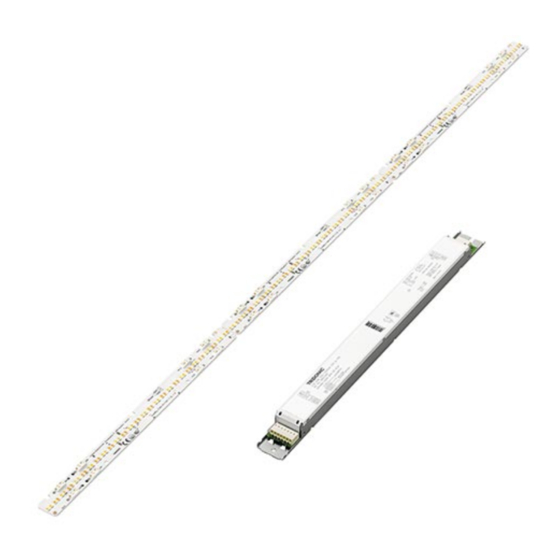
- Page 1 LED Engine Engine LLE G2 PRE KIT Technical Design-in Guide...
-
Page 2: Table Of Contents
Technical Design-in Guide Engine LLE G2 PRE KIT | 03-2020 | 1.2 | en Table of Contents 1. Introduction 4 2. Summary of the chapters 5 2.1. System overview ......................5 2.2. - Page 3 Technical Design-in Guide Engine LLE G2 PRE KIT | 03-2020 | 1.2 | en Table of Contents 8. Functions 46 8.1. DSI ........................46 8.2.
-
Page 4: Introduction
LEDs offer major benefits for general illumination tasks - they are versatile, highly energy-efficient and virtually maintenance-free. With LLE G2 PRE KIT you get a complete system solution for linear and panel lights from a single source, consisting of perfectly matched components: LED module, LED Driver in a kit package. -
Page 5: Summary Of The Chapters
Technical Design-in Guide Engine LLE G2 PRE KIT | 03-2020 | 1.2 | en Summary of the chapters To make it easier to find your way around the Design-in Guide we have grouped the information on the LLE G2 PRE KIT systems into chapters. -
Page 6: System Overview
3.1.2. Efficiency of the modules The high efficiency of LLE G2 PRE KIT results not only in energy savings but also to a reduction in the thermal load. This means that smaller heat sinks can be used and more compact luminaires can be designed. - Page 7 System Overview 3.1.3. Area of application All the components of the LLE G2 PRE KIT system comply with the protection requirements of IP20. The system is therefore suitable for indoor applications. LLE G2 PRE KIT complies with system protection class II...
-
Page 8: Operating Functions
Technical Design-in Guide Engine LLE G2 PRE KIT | 03-2020 | 1.2 | en System Overview 3.2. Operating functions LLE G2 PRE KIT offers a wide range of settings for colour temperature and dimming level. Different controllers are available. The controllers are connected directly to the LED Driver. NOTICE The factory preset for colour temperature is 2,700 K, the factory preset for light intensity is 100 %. - Page 9 Technical Design-in Guide Engine LLE G2 PRE KIT | 03-2020 | 1.2 | en System Overview NOTICE When the maximum value is reached, the next step advances directly to the minimum value. This is signaled by a short blinking. 9 / 63...
- Page 10 Technical Design-in Guide Engine LLE G2 PRE KIT | 03-2020 | 1.2 | en System Overview Changing predefined colour temperatures and dimming levels The predefined colour temperatures and dimming levels in colourTEMPERATURE mode can be changed via the masterCONFIGURATOR. Any fixed values within the two limit values of 2,700 K and 6,500 K can be selected for the colour temperature.
- Page 11 Technical Design-in Guide Engine LLE G2 PRE KIT | 03-2020 | 1.2 | en System Overview Colour temperature set Adjusting the colour temperature short press on the switch to increase the colour temperature Dimmlevel set short press on the switchDIM switch increases or decreases the dimmlevel depending on its orietation...
-
Page 12: Type Codes
Technical Design-in Guide Engine LLE G2 PRE KIT | 03-2020 | 1.2 | en System Overview 3.3. Type codes 3.3.1. Type code for modules The following type code is used to identify the modules. The table shows reference codes and their meaning for the LLE G2 PRE KIT. Reference 24x280mm 3x700... -
Page 13: Versions
3.4.1. LLE G2 PRE KIT The LLE G2 PRE KIT system is packed with completely new functions such as tunable white. The colour temperature can be changed smoothly between 2,700 K and 6,500 K to meet the specific needs of the relevant application. -
Page 14: Standards And Directives
Technical Design-in Guide Engine LLE G2 PRE KIT | 03-2020 | 1.2 | en System Overview 3.5. Standards and directives 3.5.1. Standards and directives for modules The following standards and directives were taken into consideration in designing and manufacturing the modules:... - Page 15 Technical Design-in Guide Engine LLE G2 PRE KIT | 03-2020 | 1.2 | en System Overview Energy labelling Standard Description EU Regulation No: 874/2012 "Energy labelling of electrical lamps and luminaires" 3.5.2. Standards and directives for LED Drivers The following standards and directives were taken into consideration in designing and manufacturing the LED Driver:...
-
Page 16: Mechanical Aspects
Technical Design-in Guide Engine LLE G2 PRE KIT | 03-2020 | 1.2 | en Mechanical Aspects 4.1. Installation 4.1.1. Installation details NOTICE EOS/ESD safety guidelines The device/module contains components that are sensitive to electrostatic discharge and may only be installed in the factory and on site if appropriate EOS/ESD protection measures have been taken. - Page 17 Protection measures against damage Mechanical stress LLE G2 PRE modules contain electronic components that are sensitive to mechanical stress. Such stress should be kept to an absolute minimum. In particular the following mechanical stresses should be avoided as these may cause irreversible damage:...
- Page 18 Compressive stresses The components of the LLE G2 PRE modules (circuit boards, glob-top, lenses, electronic components etc.) are sensitive to compressive stresses. The components must not be exposed to compressive stresses. If glass or Plexiglas shields are used make sure that pressure is not exerted on the glob-top.
- Page 19 Technical Design-in Guide Engine LLE G2 PRE KIT | 03-2020 | 1.2 | en Mechanical Aspects HINWEIS Contact your LED manufacturer for questions about the materials used and possible interactions and risks. Putting together a "safe list" is not possible due to the complexity of the topic. The following table lists possible contaminants for LED modules, the classes of compounds and examples of possible sources.
- Page 20 Technical Design-in Guide Engine LLE G2 PRE KIT | 03-2020 | 1.2 | en Mechanical Aspects The list shows the most commonly used materials but does not claim to be complete. Class of compounds Chemical names Occurs in hydrochloric acid...
- Page 21 During the curing period make sure that there is no tensile load on the adhesive connection of the module. Additional information LLE G2 PRE modules must not be stuck and restuck time and again without replacing the adhesive tape. Damaged adhesive tapes must be completely removed and replaced by new tapes.
- Page 22 LLE G2 PRE Kits from Tridonic are delivered in appropriate packaging. The packaging provides special protection against mechanical damage and ESD (electrostatic discharge). If you need to transport LLE G2 PRE products you should use this packaging. 4.1.3. Installation of the modules on the heat sink The LED modules are mounted onto a heat sink with 2 screws per module.
-
Page 23: Dimensional Drawings Lle G2 Pre Module
Technical Design-in Guide Engine LLE G2 PRE KIT | 03-2020 | 1.2 | en Mechanical Aspects 4.2. Dimensional drawings LLE G2 PRE module NOTICE CAD data for the modules can be downloaded from the Tridonic homepage ( www.tridonic.com ) and the relevant product page. - Page 24 Mechanical Aspects 4.3.2. LED Driver for LLE G2 PRE: LCA 100W 350–1050mA 2xDT8 lp PRE NOTICE Detailed information and CAD data for the LED Driver can be downloaded from the Tridonic homepage ( www.tridonic.com ) and the relevant product page.
-
Page 25: Electrical Aspects
LCA 100W 350-1050mA 2xDT8 lp PRE. 5.1.3. Design measures for satisfying protection class requirements Not all the components of the LLE G2 PRE KIT system comply with the SELV standard. The voltages can thus be greater than 120 V 5.1.4. Protection class II luminaires When using a LLE PRE module with NON-SELV level, the following measures are essential in order to achieve protection class II: Reinforced insulation between LLE G2 PRE module and the luminaire casing, e.g., by means of plastic casing or an additional... - Page 26 Technical Design-in Guide Engine LLE G2 PRE KIT | 03-2020 | 1.2 | en Electrical Aspects Assembly of the LLE G2 PRE module directly on the casing Grounding of the LED Driver, LLE G2 PRE module and the luminaire itself Protect all electrical contacts against mechanical contact, this can typically be achieved with optics which cannot be removed ½...
-
Page 27: Electrical Safety And Connection
LLE G2 PRE module must be supplied by a constant current LED Driver. Operation with a constant voltage LED Driver leads to irreversible damage to the modules! Wrong polarity can damage the LLE G2 PRE module. If a wire breaks or a complete module fails in the case of parallel wiring, the current passing through the other modules increases. -
Page 28: Electrical Connections
Technical Design-in Guide Engine LLE G2 PRE KIT | 03-2020 | 1.2 | en Electrical Aspects 5.3. Electrical connections 5.3.1. LLE G2 PRE module connections The LED Driver is connected to the power supply and the connections of the control lines and the LED module via push-in and spring... -
Page 29: Connections On The Led Driver
Technical Design-in Guide Engine LLE G2 PRE KIT | 03-2020 | 1.2 | en Electrical Aspects 5.4. Connections on the LED Driver Connections on the LED control gear for LLE G2 PRE Module Pin/Connection Connection on the LED Driver Design... -
Page 30: Wiring Diagrams
Technical Design-in Guide Engine LLE G2 PRE KIT | 03-2020 | 1.2 | en Electrical Aspects 5.5. Wiring diagrams 5.5.1. Wiring diagrams for LCA 50W 350-1050mA DT8 lp PRE Wiring diagram DALI for LLE PRE (700lm: with 3 to 6 modules, 1500lm: with 2 to 3 modules) Wiring diagram switchDIM und colourSWITCH für LLE PRE (700lm: with 3 to 6 modules, 1500lm: with 2 to 3... - Page 31 Technical Design-in Guide Engine LLE G2 PRE KIT | 03-2020 | 1.2 | en Electrical Aspects 5.5.2. Wiring diagrams for LCA 100W 350-1050mA 2xDT8 lp PRE Wiring diagram DALI für LLE PRE (700lm: with 6 to 12 modules, 1500lm: with 4 to 6 modules) Wiring diagram switchDIM und colourSWITCH für LLE PRE (700lm: with 6 to 12 modules, 1500lm: with 4 to 6...
- Page 32 Technical Design-in Guide Engine LLE G2 PRE KIT | 03-2020 | 1.2 | en Electrical Aspects Wiring diagram für Notlicht 32 / 63...
-
Page 33: Optical Aspects
Technical Design-in Guide Engine LLE G2 PRE KIT | 03-2020 | 1.2 | en Optical Aspects 6.1. Colour spectrum The used technology enables LEDs to be produced in special light colours or colour temperatures. This means that lighting systems can be created that are not only energy-efficient but also have excellent colour rendering. -
Page 34: Coordinates And Tolerances
Technical Design-in Guide Engine LLE G2 PRE KIT | 03-2020 | 1.2 | en Optical Aspects 6.2. Coordinates and tolerances 6.2.1. Light colours LLE G2 PRE KIT covers all the light colours below. MacAdam Ellipse: 2.700 K bis 6.500 K... - Page 35 Technical Design-in Guide Engine LLE G2 PRE KIT | 03-2020 | 1.2 | en Optical Aspects question and by a reference light source and the appearance of the samples under the different lights is compared. If there is no perceivable difference the light in question will be rated with a maximum value of 100. Differences in appearance result in a deduction from the maximum value.
-
Page 36: Sdcm
Technical Design-in Guide Engine LLE G2 PRE KIT | 03-2020 | 1.2 | en Optical Aspects 6.4. SDCM The human eye can not only recognise different colours along the black body curve, but also deviations above or below this line. If an LED has a colour temperature of 2,700 K , but is not directly located on the black body curve, it can be perceived as different from another LED with the same colour temperature. - Page 37 Technical Design-in Guide Engine LLE G2 PRE KIT | 03-2020 | 1.2 | en Optical Aspects 6.7.1. Chromaticity coordinate LEDs exhibit variations in terms of their exact shade of colour. This means that different “white” LEDs will all shine in a colour that is within the white colour spectrum.
- Page 38 Technical Design-in Guide Engine LLE G2 PRE KIT | 03-2020 | 1.2 | en Optical Aspects 6.7.3. Eye safety Risk group Evaluation Actinic UV E (200 - 400 nm) Risk group 0 Near UV E (315 - 400 nm) Risk group 0...
-
Page 39: Beam Characteristics
6.8.1. Lenses With LLE G2 PRE modules, the luminaire can be produced with either a diffuser or reflectors. There must be a minimum distance of 3 mm between the active parts and the conductive optical parts, e.g., reflector to the LED module. - Page 40 Technical Design-in Guide Engine LLE G2 PRE KIT | 03-2020 | 1.2 | en Optical Aspects 6.8.2. Beam characteristics of the LLE G2 PRE module Intense Batwing Asymmetric Double asymmetric 40 / 63...
-
Page 41: Thermal Aspects
7.1.1. Effect of cooling on the life of the modules The modules of the LLE G2 PRE KIT system have been designed for operation with a passive heat sink and can be mounted directly on such a suitable heat sink. - Page 42 Technical Design-in Guide Engine LLE G2 PRE KIT | 03-2020 | 1.2 | en Thermal Aspects LLE G2 24x280mm 700lm PRE Forward current tp temperature L90 / F10 L90 / F50 L80 / F10 L80 / F50 L70 / F10...
-
Page 43: Passive Cooling
7.2.1. Effect of cooling on the life of the modules The modules of the LLE G2 PRE KIT system have been designed for operation with a passive heat sink and can be mounted directly on such a suitable heat sink. - Page 44 All the values refer to a maximum surface temperature tc = 65 °C and 350 mA. The actual cooling surface can deviate depending on the material, design, external influences and the installation situation. A thermal connection between LLE G2 PRE Module and the heat sink using heat-conducting paste or heat-conducting adhesive foil is essential.
- Page 45 Technical Design-in Guide Engine LLE G2 PRE KIT | 03-2020 | 1.2 | en Thermal Aspects In practice, thermocouples (e.g. B&B Thermotechnik, K-type thermocouple) have proved successful. Such thermocouples can be attached directly to the t point with heat-resistant adhesive tape or a suitable adhesive. The measured values are recorded by an electronic thermometer (e.g., "FLUKE 51", VOLTCRAFT K202 data logger).
-
Page 46: Functions
Technical Design-in Guide Engine LLE G2 PRE KIT | 03-2020 | 1.2 | en Functions 8.1. DSI 8.1.1. Description DSI (Digital Serial Interface) enables DSI control gear to be controlled. The DSI line can be wired separately via a two-core cable or together with the mains cable in a five-core cable. -
Page 47: Switchdim
Technical Design-in Guide Engine LLE G2 PRE KIT | 03-2020 | 1.2 | en switchDIM 8.2. switchDIM 8.2.1. Description With the switchDIM function it is possible to use the mains voltage as a control signal. The phase of a simple standard mains voltage push button is connected to the terminal marked DA/L and the neutral conductor is connected to the terminal marked DA/N. - Page 48 Technical Design-in Guide Engine LLE G2 PRE KIT | 03-2020 | 1.2 | en switchDIM Procedure: Switch the device on/off by briefly actuating the push button or Dim the device by holding down the push button Synchronising devices If the devices in a system do not operate synchronously the devices must be synchronised, i.e. put in the same status (on/off).
- Page 49 Technical Design-in Guide Engine LLE G2 PRE KIT | 03-2020 | 1.2 | en switchDIM Four-pole wiring Configuration: Phase (L), neutral (N), earth (PE), control line (L') Benefits: No need for a control line thanks to bridging terminal 8 and the N-connection of the luminaire...
- Page 50 Technical Design-in Guide Engine LLE G2 PRE KIT | 03-2020 | 1.2 | en switchDIM ½ CAUTION! For five-pole wiring the neutral conductor must be connected to DA/N. This prevents 400 V being applied between adjacent terminals if a different phase is used for the control input.
-
Page 51: Power-Up Fading
Technical Design-in Guide Engine LLE G2 PRE KIT | 03-2020 | 1.2 | en Power-up fading 8.3. Power-up Fading 8.3.1. Description The power-up fading function offers the opportunity to realise a soft start. The soft start will be applied at turning on the mains and at starts by switchDIM. -
Page 52: Dali
The DALI standard is defined in IEC 62386. A test procedure standardised by the DALI Activity Group ensures compatibility between products from different manufacturers. Tridonic products have undergone this test and meet all the requirements. This is indicated by the logo of the DALI Activity Group on the device. - Page 53 ("enhanced DALI") offers extended DALI commands. They can be used to activate specific commands of the LED Driver. The masterCONFIGURATOR software works with eD commands. These commands are Tridonic specific. They are not part of the DALI standard and are not publicly available.
-
Page 54: Constant Light Output
Technical Design-in Guide Engine LLE G2 PRE KIT | 03-2020 | 1.2 | en Constant Light Output 8.5. Constant Light Output 8.5.1. Description The light output of an LED module reduces over the course of its life. The Constant Light Output function compensates for this natural decline by constantly increasing the output current of the LED Driver throughout its life. - Page 55 Technical Design-in Guide Engine LLE G2 PRE KIT | 03-2020 | 1.2 | en Constant Light Output Setting Required intensity and Expected LED life Open dialog box "Tridonic-specific configuration" Click tab "CLO and OTL" Enter values in input fields "Required intensity" and "Expected LED life"...
-
Page 56: Dc Recognition
Technical Design-in Guide Engine LLE G2 PRE KIT | 03-2020 | 1.2 | en DC recognition 8.6. DC recognition 8.6.1. Description In emergency light systems with central battery supply the DC recognition function uses the input voltage to detect that emergency mode is in place. -
Page 57: Dimming On Dc
Technical Design-in Guide Engine LLE G2 PRE KIT | 03-2020 | 1.2 | en Dimming on DC 8.7. Dimming on DC 8.7.1. Description If Dimming on DC is activated the requirements of the DC recognition function are ignored. Even if DC is detected the LED Driver... -
Page 58: Intelligent Temperature Guard
Technical Design-in Guide Engine LLE G2 PRE KIT | 03-2020 | 1.2 | en Intelligent Temperature Guard 8.8. Intelligent Temperature Guard ½ WARNING! The maximum t temperature is the maximum permitted in terms of life time. Operating the LED Drivers above the permitted t temperature is not allowed. - Page 59 Technical Design-in Guide Engine LLE G2 PRE KIT | 03-2020 | 1.2 | en Intelligent Temperature Guard Power Power reduction is dependent on temperature: reduction Power reduction continues if temperature still rises process and Power reduction stops if temperature does not rise anymore or if maximum power reduction is reached...
-
Page 60: Ordering Information And Sources
Technical Design-in Guide Engine LLE G2 PRE KIT | 03-2020 | 1.2 | en Ordering information and sources 9.1. Article numbers 9.1.1. LLE G2 PRE KIT CRI > 90 (calibrated kit) System Colour- Typ. luminous Typ. power efficacy Order Type... - Page 61 Tolerance range for optical data: ±5 % and tolerance range for electrical data: ±5 %. 9.1.2. Suitable controllers Tridonic offers a comprehensive range of DALI-compatible products. All the devices specified here support DALI Device Type 6 and therefore guarantee effective use of LLE PRE KIT.
-
Page 62: Product Application Matrix
Technical Design-in Guide Engine LLE G2 PRE KIT | 03-2020 | 1.2 | en Ordering information and sources 9.2. Product application matrix Whether you are looking for wide-area lighting or focused accent lighting, our wide range of PRE products will help you create an individual atmosphere and highlight specific areas exactly as you want. -
Page 63: Reference List
Technical Design-in Guide Engine LLE G2 PRE KIT | 03-2020 | 1.2 | en Reference list 10.1. Related documents Data sheet Module LLE G2 PRE: https://www.tridonic.com/com/en/download/data_sheets/Module_LLE_G2_premium_en.pdf System data sheet Module Stark LLE PRE: https://www.tridonic.com/com/en/download/data_sheets/TALEXXengine_STARK_LLE_premium_Systemdatasheet_en.pdf Engine STARK LLE PRE – Technical Design-in Guide: https://www.tridonic.com/com/en/download/technical/LLE_PRE_Kit_guide_en.pdf...
Need help?
Do you have a question about the LLE G2 PRE and is the answer not in the manual?
Questions and answers