Table of Contents
Advertisement
Quick Links
Dear customer
st
LAPIS Semiconductor Co., Ltd. ("LAPIS Semiconductor"), on the 1
day of October,
2020, implemented the incorporation-type company split (shinsetsu-bunkatsu) in which
LAPIS established a new company, LAPIS Technology Co., Ltd. ("LAPIS
Technology") and LAPIS Technology succeeded LAPIS Semiconductor's LSI business.
Therefore, all references to "LAPIS Semiconductor Co., Ltd.", "LAPIS Semiconductor"
and/or "LAPIS" in this document shall be replaced with "LAPIS Technology Co., Ltd."
Furthermore, there are no changes to the documents relating to our products other than
the company name, the company trademark, logo, etc.
Thank you for your understanding.
LAPIS Technology Co., Ltd.
October 1, 2020
Advertisement
Table of Contents

Subscribe to Our Youtube Channel
Related Manuals for LAPIS Semiconductor ML62Q1367


Summary of Contents for LAPIS Semiconductor ML62Q1367
- Page 1 LAPIS established a new company, LAPIS Technology Co., Ltd. (“LAPIS Technology”) and LAPIS Technology succeeded LAPIS Semiconductor’s LSI business. Therefore, all references to "LAPIS Semiconductor Co., Ltd.", "LAPIS Semiconductor" and/or "LAPIS" in this document shall be replaced with "LAPIS Technology Co., Ltd."...
- Page 2 FEBL62Q1367RB-01 ML62Q1367 Reference Board User's Manual Issue Date: May 23, 2018...
- Page 3 US Export Administration Regulations and the Foreign Exchange and Foreign Trade Act. 13) This document, in part or in whole, may not be reprinted or reproduced without prior consent of LAPIS Semiconductor. Copyright 2018 LAPIS Semiconductor Co., Ltd.
-
Page 4: Table Of Contents
ML62Q1367 Reference Board User’s Manual Table of Contents Overview ................................1 1.1. Features ................................1 1.2. ML62Q1367 Reference Board Outline Diagram .................... 2 Function of ML62Q1367 Reference Board ......................3 2.1. Power Circuit ..............................3 2.2. Connection for EASE1000 (CNE) ......................... 4 2.3. - Page 5 ML62Q1367 Reference Board User’s Manual Preface This manual describes about the ML62Q1367 Reference Board : RB-D62Q1367TB32. Refer to following documents when necessary. – ML62Q1300 Group User’s Manual Provides the detailed information about the microcontroller ML62Q1300 Group. – EASE1000 User’s Manual Provides the information on how to use the On-chip emulator EASE1000.
-
Page 6: Overview
1. Overview 1.1. Features The ML62Q1367 Reference Board can be used for learning ‘how to use’ the ML62Q1367, on which the user needs to provide additional external components if necessary. By using the ML62Q1367 Reference Board together with the LAPIS Semiconductor’s on-chip emulator EASE1000 and the provided software development environment, the user can develop... -
Page 7: Ml62Q1367 Reference Board Outline Diagram
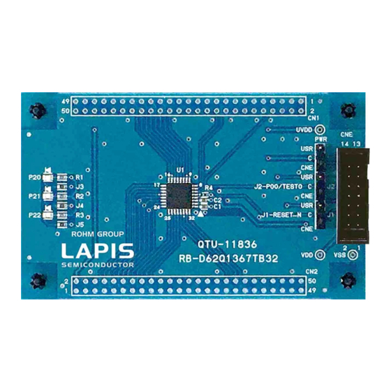
ML62Q1367 Reference Board User’s Manual 1.2. ML62Q1367 Reference Board Outline Diagram Fig. 1 shows the ML62Q1367 Reference Board. Jumper ・PWR ・J2 ・J1 ・P20 ・P21 ・P22 Fig. 1 ML62Q1367 Reference Board Outline Diagram FEBL62Q1367RB... -
Page 8: Function Of Ml62Q1367 Reference Board
ML62Q1367 Reference Board User’s Manual 2. Function of ML62Q1367 Reference Board 2.1. Power Circuit The input toV can be selected from 3.3VOUT of EASE1000 or CN1_3pin / CN2_2pin by PWR jumper. VTref ML62Q1367 3.3VOUT 2,4,6,8,10,12 UVDD Fig. 2 Power Circuit [Note] The power supply ON/OFF procedure in case of setting PWR jumper to the USR-side when using EASE1000. -
Page 9: Connection For Ease1000 (Cne)
ML62Q1367. 2.3. LED (P20, P21, P22) The P20-P22 pins of the ML62Q1367 are ports that can directly drive LED. The Ports are connected to the LEDs through jumper-chip. Remove the jumper-chip when not using the LEDs. -
Page 10: User Interface
ML62Q1367 Reference Board User’s Manual 3. User Interface Table 2 shows the pin list of the ML62Q1367 Reference Board user interface connection CN1 and CN2. Table 2 ML62Q1367 Reference Board CN1/CN2 NAME NAME NAME NAME N.C. N.C. N.C. N.C. N.C. -
Page 11: Precaution For Usage
(1) The ML62Q1367 Reference Board is an unfinished product and intended for research and development and for expert use in the research and development facility only. The ML62Q1367 Reference Board is not intended to be used for volume production or parts thereof. -
Page 12: Pcb Specification, Bom And Schematic
ML62Q1367 Reference Board User’s Manual 5. PCB specification, BOM and Schematic 5.1. ML62Q1367 Reference Board PCB specification Fig. 7 shows the Reference Board PCB dimensional outline diagram and layout of components. PCB part number: RB-D62Q1367TB32 Dimension: 55.88mm x 93.98mm Fig. 5 Reference Board PCB dimensional outline diagram and layout of components (Top view) -
Page 13: Ml62Q1367 Reference Board Bom
Using CN1 and CN2, the diameter of connector pin should use the connector below 0.8mm, such as 0.5mm. The parts may be changed into another parts with equivalent part special quality. 5.3. ML62Q1367 Reference Board Schematic The next page shows the schematic of ML62Q1367 Reference Board FEBL62Q1367RB... - Page 14 ML62Q1367 Reference Board User’s Manual FEBL62Q1367RB...
-
Page 15: Revision History
ML62Q1367 Reference Board User’s Manual Revision History Page Document No. Issue Date Description Previous Edition Edition FEBL62Q1367RB-01 May 23, – – First edition. 2018 FEBL62Q1367RB...
Need help?
Do you have a question about the ML62Q1367 and is the answer not in the manual?
Questions and answers