Advertisement
Available languages
Available languages
Quick Links
Operator's Manual
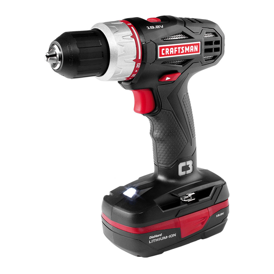
C3 1/2" DRILL/DRIVER
Model No. 5275.1
ѥ
WARNING: To reduce the risk of injury,
the user must read and understand the
Operator's Manual before using this product.
Sears Brands Management Corporation, Hoffman Estates,
IL 60179 U.S.A.
www.craftsman.com
• WARRANTY
• SAFETY
• DESCRIPTION
• ASSEMBLY
• OPERATION
• MAINTENANCE
• ESPAÑOL
Advertisement

Related Manuals for Craftsman 5275.1


Summary of Contents for Craftsman 5275.1
- Page 1 Operator’s Manual C3 1/2" DRILL/DRIVER Model No. 5275.1 • WARRANTY • SAFETY • DESCRIPTION • ASSEMBLY ѥ WARNING: To reduce the risk of injury, • OPERATION the user must read and understand the • MAINTENANCE Operator’s Manual before using this product.
- Page 2 This ONE YEAR warranty is void if this product is ever used while providing commercial services or if rented to another person. For 90 DAY commercial and rental use terms, see the Craftsman warranty web page. This warranty gives you specific legal rights, and you may also have other rights which vary from state to state.
- Page 3 ѥ DANGER: People with electronic devices, such as pacemakers, should consult their physician(s) before using this product. Operation of electrical equipment in close proximity to a heart pacemaker could cause interference or failure of the pacemaker. ѥ WARNING: Some dust created by power sanding, sawing, grinding, drilling and other construction activities contains chemicals known to the state of California to cause cancer, birth defects or other reproductive harm.
- Page 4 Minutes SAFETY SYMBOLS The purpose of safety symbols is to attract your attention to possible dangers. Alternating Current The safety symbols and the explanations with them deserve your careful attention and understanding. The symbol warnings do not, by themselves, eliminate any danger. The instructions and warnings they give are no substitutes Direct Current for proper accident prevention measures.
- Page 5 SAVE THESE INSTRUCTIONS Some of these following symbols may be used on this tool. Please study them and learn their meaning. Proper interpretation of these symbols will allow you to operate the tool better and more safely. SYMBOL NAME DESIGNATION/EXPLANATION Volts Voltage Amperes...
- Page 6 SAFETY INSTRUCTIONS GENERAL POWER TOOL SAFETY WARNINGS ѥ WARNING: Read all safety warnings and instructions. Failure to follow the warnings and instructions may result in electric shock, fire and/or serious injury. Save all warnings and instructions for future reference. The term “power tool” in the warnings refers to your mains-operated (corded) power tool or battery-operated (cordless) power tool.
- Page 7 PERSONAL SAFETY • Stay alert, watch what you are doing and use common sense when operating a power tool. Do not use tool while tired or under the influence of drugs, alcohol, or medication. A moment of inattention while operating power tools may result in serious personal injury. •...
- Page 8 • Keep cutting tools sharp and clean. Properly maintained cutting tools with sharp cutting edges are less likely to bind and are easier to control. • Use the power tool, accessories, tool bits, etc. in accordance with these instructions, taking into account the working conditions and the work to be performed.
- Page 9 DESCRIPTION KNOW YOUR DRILL/DRIVER (Fig. 1) Two-Speed Gearbox Switch Fig. 1 Torque-Adjustment Ring Keyless Chuck Chuck Jaws Direction-of-Rotation Selector (Forward/ Variable-Speed Center-Lock/Reverse) Trigger Switch LED Worklight Bit Storage PRODUCT SPECIFICATIONS Motor 19.2 Volt DC Chuck 1/2 in. (13mm) No-load Speed LO 0-350/min.
- Page 10 ADJUSTABLE TORQUE The drill/driver has a 21-position clutch: 1 drill position and 20 torque positions. TWO-SPEED GEARBOX The two-speed gearbox is designed for drilling or driving at LO or HI speeds. A slide switch is located on top of your drill/driver for selecting the appropriate speed.
- Page 11 ASSEMBLY ѥ WARNING: If any parts are broken or missing, do not attempt to attach the battery pack or operate the drill/driver until the broken or missing parts are replaced. Failure to do so could result in possible serious injury. ѥ...
- Page 12 OPERATION This product will accept Craftsman C3 19.2V lithium-ion battery packs. For complete charging instructions, refer to the Operator’s Manual for the battery packs and chargers. ѥ WARNING: To prevent accidental starting that could cause serious personal injury, always remove the battery pack from the tool when assembling parts, making adjustments, installing or removing bits, cleaning, or when it is not in use.
- Page 13 TRIGGER SWITCH (Fig. 3) Fig. 3 To turn the drill/driver ON, depress the trigger switch. To turn it OFF, release the trigger switch. Variable-Speed VARIABLE SPEED (Fig. 3) Trigger Switch The variable-speed trigger switch delivers higher speed with increased trigger pressure and lower speed with decreased trigger pressure.
- Page 14 KEYLESS CHUCK (Fig. 5) Fig. 5 RELEASE The drill/driver has a keyless chuck to tighten or release bits in the chuck jaws. The arrows on the chuck indicate the direction in Chuck Jaws which to rotate the chuck in order to GRIP (tighten) or RELEASE the chuck jaws on the bit.
- Page 15 ADJUSTABLE-TORQUE Fig. 7 Torque- CLUTCH (Fig. 7) Adjustment To decrease torque Ring The higher the torque setting, the more force the drill/driver produces to turn an object in either LO or HI rotation speed. When using the drill/driver for different driving applications, increase or decrease the torque To increase torque in order to do the job and help...
- Page 16 LED WORKLIGHT (Fig. 9) Fig. 9 The LED worklight, located on the base of the drill/driver, will illuminate when the trigger switch is depressed. This provides additional light on the surface of the workpiece. The LED worklight will turn off when the trigger switch is released.
- Page 17 REMOVING BITS (Fig. 12) Fig. 12 RELEASE Remove the battery pack Lock the trigger switch on the drill/driver by placing the direction-of-rotation selector in the center position. Open the chuck jaws. Rotate the chuck in the Chuck Jaws direction of the arrow marked Keyless Chuck RELEASE to loosen the chuck jaws.
- Page 18 NOTICE: This drill/driver is equipped with an electric brake. When the brake is functioning properly, sparks may be visible through the vent slots in the housing. This is normal and results from the action of the brake. WOOD DRILLING For maximum performance, use wood-boring brad- point drill bits (available separately) or brad-point bits (available separately) for wood drilling.
- Page 19 ѥ WARNING: When servicing, use only identical Craftsman replacement parts. Use of any other parts may create a hazard or cause product damage. To ensure safety and reliability, all repairs should be performed by a qualified service technician.
- Page 20 Open the chuck jaws and Fig. 16 remove the hex key. Use a Philips screwdriver (available separately), to remove the Chuck Jaws chuck screw by turning it in a clockwise direction. Keyless Chuck NOTICE: The chuck screw has Mallet left-handed threads. Insert the hex key into the chuck and tighten the Hex Key...
- Page 21 TROUBLESHOOTING PROBLEM CAUSE SOLUTION The drill/driver does Battery is depleted Charge the battery not work Bit cannot be installed Chuck is not open Open the chuck Be sure that cooling Clean and clear the vents. Motor is overheating vents are free from saw Do not cover vents with dust and obstacles hand during operation...
- Page 22 PARTS LIST 1/2" Drill/Driver Model Number 5275.1 The Model Number will be found on the nameplate attached to the tool. Always mention the Model Number when ordering parts for this tool. To order parts, call 1-888-331-4569...
- Page 23 PARTS LIST 1/2" Drill/Driver Model Number 5275.1 The Model Number will be found on the nameplate attached to the tool. Always mention the Model Number when ordering parts for this tool. To order parts, call 1-888-331-4569. Part No Part Name 5620488000 Screw (L.H.)
- Page 25 Manual del Propietario Perforadora/atornilladora de 1/2” C3 Modelo Nº. 5275.1 • GARANTÍA • SEGURIDAD • DESCRIPCIÓN • MONTA JE ѥ ADVERTENCIA: Para reducir el riesgo de • OPERACIÓN lesiones, el usuario debe leer y comprender el • MANTENIMIENTO Manual del Propietario antes de usar •...
- Page 26 Si desea obtener detalles sobre la cobertura de garantía para obtener un reemplazo sin costo, visite la página web: www.craftsman.com/warranty La presente garantía de UN AÑO quedará anulada si este producto se usa para brindar servicios comerciales o si se alquila a terceros. Para consultar los términos de uso comercial y de alquiler de 90 DÍAS, visite la página web...
- Page 27 ѥ PELIGRO: La gente con los accesorios electrónicos, como los estimuladores cardíacos, deben consultar sus médicos antes de usar esto producto. La operación de los equipos eléctricos cerca de un estimulador cardiaco puede causar la interferencia o la avería del estimulador cardíaco. ѥ...
- Page 28 Minutes SÍMBOLOS DE SEGURIDAD Alternating Current El objeto de los símbolos de seguridad es atraer su atención sobre posibles peligros. Los símbolos de seguridad y las explicaciones junto a ellas ameritan su cuidadosa atención y comprensión. Los símbolos de advertencia no eliminan los peligros por sí...
- Page 29 GUARDE ESTAS INSTRUCCIONES Algunos de los siguientes símbolos pueden utilizarse en esta herramienta. Tenga a bien estudiarlos y aprender su significado. Una interpretación adecuada de estos símbolos le permitirá operar la herramienta de una manera mejor y más segura. SÍMBOLO NOMBRE DESIGNACIÓN / EXPLICACIÓN Voltios...
- Page 30 INSTRUCCIONES DE SEGURIDAD ADVERTENCIAS GENERALES DE SEGURIDAD DE LAS HERRAMIENTAS ELÉCTRICAS ѥ ADVERTENCIA: Lea y comprenda todas las instrucciones. No seguir todas las instrucciones listadas a continuación puede generar una descarga eléctrica, un incendio y/o graves lesiones corporales. El término “herramienta eléctrica” de todas las advertencias listadas a continuación hacen referencia a herramientas eléctricas con cable o herramientas eléctricas operadas a batería (inalámbricas).
- Page 31 • Cuando utilice una herramienta eléctrica al aire libre, use un cable de extensión especial para uso al exterior. El uso de un cable adecuado para el aire libre reduce el riesgo de una descarga eléctrica. • Si no puede evitar el uso de una herramienta eléctrica en un lugar húmedo, utilice un suministro de energía protegido por un interruptor de circuito con descarga a tierra (GFCI, por sus siglas en inglés).
- Page 32 USO Y CUIDADO DE LA HERRAMIENTA ELÉCTRICA • No fuerce la herramienta eléctrica. Use la herramienta eléctrica correcta para su aplicación. La herramienta eléctrica correcta hará mejor el trabajo y de manera más segura cuando se usa en la clasificación para la cual fue diseñada. •...
- Page 33 • Si se la somete a malas condiciones, puede salir líquido de la batería; evite el contacto. Si ocurre un contacto accidental, enjuague con agua. Si el líquido ingresa a sus ojos, busque ayuda médica. El líquido que sale de la batería puede provocar irritación o quemaduras. SERVICIO •...
- Page 34 DESCRIPCIÓN CONOZCA SU PERFORADORA/ATORNILLADORA (Fig. 1) Interruptor de la caja de dos Fig. 1 Anillo de ajuste de torque velocidades Portabrocas sin llave Horquillas del portabrocas Selector de la dirección de rotación (adelante/ Interruptor de gatillo de bloqueo centro/reversa) velocidad variable Luz de trabajo LED Gancho de la broca ESPECIFICACIÓN DE PRODUCTO...
- Page 35 TORQUE AJUSTABLE La perforadora/atornilladora cuenta con un embrague de 21 posiciones. Tiene 1 posición para perforadora y 20 para torque. CAJA DE DOS VELOCIDADES La caja de dos velocidades está diseñada para perforar o atornillar en velocidades LO (baja) o HI (alta). En la parte superior de su perforadora/ atornilladora hay un interruptor deslizable que se utiliza para seleccionar la velocidad apropiada.
- Page 36 MONTAJE ѥ ADVERTENCIA: Si falta alguna pieza o si alguna pieza está rota, no trate de enchufar el cable de energía u operar la perforadora/atornilladora hasta que se reemplacen las piezas faltantes o rotas. No hacerlo puede provocar una lesión personal grave.
- Page 37 OPERATION Este producto acepta paquetes de baterías de ion de litio Craftsman C3 de 19.2V. Para las instrucciones de carga completas, consulte los Manuales del Operador correspondientes a los paquetes de baterías y cargadores. ѥ ADVERTENCIA: Para evitar un arranque accidental que podría provocar lesiones personales graves, siempre desconecte el paquete de baterías de...
- Page 38 INTERRUPTOR DE GATILLO Fig. 3 (Fig. 3) Para encender (ON) la perforadora/ atornilladora, presione el interruptor de gatillo. Para apagarla (OFF), suelte el interruptor de gatillo. Interruptor de gatillo de VELOCIDAD VARIABLE velocidad variable (Fig. 3) El gatillo de velocidad variable ofrece una velocidad mayor con Fig.
- Page 39 DESBLOQUEAR PORTABROCAS SINLLAVE Fig. 5 (liberar) (Fig. 5) La perforadora/atornilladora cuenta con un portabrocas sin llave para ajustar o liberar brocas Horquillas del de las horquillas del portabrocas. portabrocas Las flechas del portabrocas indican la dirección en la que BLOQUEAR debe girarse el cuerpo del (ajustar) portabrocas para TOMAR (ajustar)
- Page 40 EMBRAGUE DE TORQUE Fig. 7 Para AJUSTABLE (Fig. 7) aumenta el Para disminuir torque Cuanto mayor la configuración el torque de torque, mayor la potencia que produce la perforadora/ atornilladora para girar un objeto en velocidad de rotación baja (LO) o alta (HI). Cuando se utilice la perforadora/ atornilladora Anillo de ajuste de torque para diferentes aplicaciones de...
- Page 41 LUZ DE TRABAJO LED Fig. 9 (Fig. 9) La luz de trabajo LED, ubicada en la base de la perforadora/ atornilladora, se ilumina cuando se presiona el interruptor de gatillo. Esto brinda iluminación adicional sobre la superficie de la pieza de trabajo para poder trabajar en áreas de baja Luz de trabajo LED iluminación.
- Page 42 Introduzca una broca. ѥ ADVERTENCIA: Asegúrese de colocar la broca directamente dentro de las horquillas del portabrocas. No coloque la broca dentro de las horquillas del portabrocas en ángulo y ajuste. Esto podría generar que la broca salga disparada del taladro/atornillador durante el uso, provocando lesiones personales graves durante el uso o daños al portabrocas.
- Page 43 atornilladora firmemente y coloque la broca en el punto donde va a efectuar la perforación. Presione el interruptor de gatillo para encender la perforadora/atornilladora. Introduzca la broca de la perforadora en la pieza de trabajo, aplicando sólo la fuerza suficiente para que la broca siga cortando. No fuerce la perforadora/atornilladora ni aplique presión lateral para alargar un orificio.
- Page 44 PERFORACIÓN EN METAL Para un desempeño máximo, utilice brocas de acero de alta velocidad o brocas para madera de punta fina. Cuando perfore metales, utilice aceite liviano en la broca para evitar el sobrecalentamiento. El aceite prolonga la vida útil de la broca y aumenta la acción de perforación.
- Page 45 MANTENIMIENTO ѥ ADVERTENCIA: Para evitar una lesión personal grave, siempre quite el paquete de baterías de la herramienta cuando la limpie o realice alguna clase de mantenimiento. ѥ ADVERTENCIA: Siempre utilice gafas de seguridad con protecciones laterales cuando utilice aire comprimido para limpiar la herramienta. Si durante la operación se genera mucho polvillo, también use una máscara antipolvillo.
- Page 46 Introduzca una llave Fig. 16 hexagonal de 5/16 pulg. o más grande dentro Horquillas del del portabrocas de la portabrocas perforadora/atornilladora y Portabrocas ajuste bien las horquillas. sin llave Golpee la llave hexagonal con Martillo un martillo en dirección de las agujas del reloj.
- Page 47 ѥ ADVERTENCIA: Para evitar una lesión personal grave, siempre quite el paquete de baterías de la herramienta y desenchufe el cargador cuando realiza una limpieza o alguna clase de mantenimiento. IDENTIFICACIÓN Y SOLUCIÓN DE PROBLEMAS PROBLEMA CAUSA SOLUCIÓN La perforadora/ atornilladora no La batería está...
Need help?
Do you have a question about the 5275.1 and is the answer not in the manual?
Questions and answers