
Related Manuals for Hirschmann PAT EI65/0005


Summary of Contents for Hirschmann PAT EI65/0005
- Page 1 HIRSCHMANN LENGTH-ANGLE-RADIUS-LOAD INDICATING SYSTEM EI65/0005 OPERATOR’S MANUAL P/N 056-065-190-005, Rev. C, 6/15/00...
- Page 3 Operator’s Manual EI65 / 0005 NOTICE The information in this document is subject to change without notice. PAT makes no warranty of any kind with regard to this material, including, but not limited to the implied warranties of merchantability and fitness for a particular purpose. PAT shall not be liable for errors contained herein or for incidental or consequential damages in connection with the furnishing, performance...
-
Page 5: Table Of Contents
Operator’s Manual EI65 / 0005 Table of Contents 1. GENERAL INFORMATION ......................1 2. WARNINGS........................... 1 3. SYSTEM DESCRIPTION ......................2 3.1 System Function ......................2 3.2 Operating Console ..................... 5 3.3 Control Identification ....................6 4. PROGRAMMING PROCEDURE....................9 4.1 Startup Procedure ...................... -
Page 7: General Information
General Information 1. GENERAL INFORMATION The PAT Length-Angle-Radius-Load Indicator System EI65 has been designed to provide the crane operator with the essential information required to enable the machine to be used within its design parameters. The EI65 System indicates the length and angle of the boom, tip height, working radius and the total calculated weight being lifted by the crane. -
Page 8: System Description
Operator’s Manual EI65 / 0005 3. SYSTEM DESCRIPTION The PAT EI65 System consists of an operating console with a central microprocessor unit, length/angle sensor, force transducers and anti-two block switches. Boom length and boom angle is registered by the length/angle sensor mounted inside the cable reel, which is mounted on the boom. - Page 9 Programming Procedure Figure 1: PAT System EI65 Components of the Telescopic Crane 1. Console 2. Cable Reel 3. Linerider or Force Transducer * 4. A2B Switch * The load sensor depends on the system and crane options. Refer to Installation Manual 031-300-190-008 for system kit options.
- Page 10 Operator’s Manual EI65 / 0005 Figure 2: PAT System EI65 Components of the Lattice Crane 1. Console 2. Cable Reel 3. Linerider or Force Transducer* 4. A2B Switch 5. Angle Sensor * The load sensor depends on the system and crane options.
-
Page 11: Operating Console
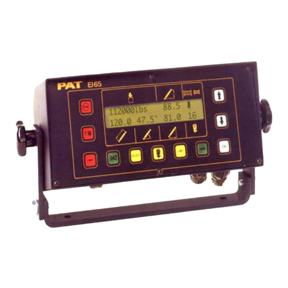
Programming Procedure 3.2 Operating Console The console has 2 functions: • terminal for input of instructions and information to the system by the crane operator • display of crane data and information The operating console is located in the operator’s cabin in front of the operator. This unit contains different displays and controls, which are described in Section 3.3. -
Page 12: Control Identification
Operator’s Manual EI65 / 0005 3.3 Control Identification The above figure illustrates the controls and displays of the EI65 Operating Console. The numbers of the illustration correspond to the numbers in the following list, which describes the function of each control. - Page 13 Programming Procedure “Select” Button The button “Select” (6) is used for indicating and setting the values of the Operating conditions. SELECT After pressing this button the display indicates a part of the “Select Menu”. It is possible to move through the different points and pages of the menu step by step by pushing the “DOWN”...
- Page 14 Operator’s Manual EI65 / 0005 11 “Down” Button The button “Down” (11) is used to get a decrease of a numerical value at the display during the programming and setting procedures and to move through the different menus in “Down” direction. The instruction to use this button will be given on the display. 12 “Up”...
-
Page 15: Programming Procedure
Programming Procedure 4. PROGRAMMING PROCEDURE During the startup phase the PAT System EI65 automatically starts with a programming procedure which relies on the correct entry by the crane operator. This procedure consists of three parts: • Startup Procedure • Setting operating configuration of the crane •... -
Page 16: Setting Operating Configuration Of The Crane
Operator’s Manual EI65 / 0005 4.2 Setting Operating Configuration of the Crane Note: Only calibrated operating selections, i.e. extension and/or jibs, will appear in the following operating configuration selection. Step 1 To enter new values the “Select” (6) button has to be pressed. The DOWN (11) button can be pressed to skip a step in the following procedure. - Page 17 Programming Procedure Step 7 The display shows the previously programmed or default length of jib 1. Enter a JIB LGTH_1: new jib length, using the “UP” (12) or “DOWN” (11) buttons. If no jib 1 is used USE ↓↑ OR OK the value 0.0 has to be selected.
- Page 18 Operator’s Manual EI65 / 0005 Step 12 Press Button “OK” (10) to enter the number of reevings (parts of line) REEVING? being used. If the operator wants to continue with the previously programmed or default number of reevings, press “DOWN” (11) button. PUSH ↓...
-
Page 19: Setting Of Reevings
Programming Procedure 4.2.1 Setting of Reevings The operator can activate the setting procedure by pushing the button “Reevings/Hoist Winch” (7). After pushing the button one time an asterisk will appear on the display beside the number of reevings, indicating that the procedure of setting the reevings is activated. To enter a new number of reevings the operator has to select the value by pushing the buttons “UP”... -
Page 20: Activating And Setting Of Preset Limits
Operator’s Manual EI65 / 0005 4.3 Activating and Setting of Preset Limits The PAT System EI65 is equipped with the following presets: • limit for maximum hook load • limits for maximum and minimum boom angle, boom length and working radius. The operator has the option to activate a maximum and minimum limit of one of the above geometric dimensions. -
Page 21: Setting Of Boom Angle Presets
Programming Procedure Step 3 The maximum boom length preset value is displayed, use the “UP” (12) and MAX. LIMIT: “DOWN” (11) buttons to change the displayed value to your desired limit. USE ↑↓ OR OK Push Button “OK” (10) for next step. Step 4 Verification of the previously set values for maximum and minimum boom MAX. -
Page 22: Setting Of Boom Radius Presets
Operator’s Manual EI65 / 0005 4.3.3 Setting of Boom Radius Presets Step 1 This message appears after pushing the “LIMIT” (8) button and pressing RADIUS LIMIT? the “DOWN” (11) button to scroll through the limits. To set a minimum PUSH ↓ OR OK and maximum boom radius limit press the “OK”... -
Page 23: Setting Of Boom Load Presets
Programming Procedure Step 4 Verification of the previously set values for maximum and minimum boom MAX. LIMIT: height presets are displayed. If the values are incorrect press “OK” (10) button MIN. LIMIT: and restart the limit preset procedure. Pressing “OK” will store the preset values and return to the working screen. -
Page 24: Pre-Operation Inspection
Operator’s Manual EI65 / 0005 5. PRE-OPERATION INSPECTION Prior to operating the crane, the following checks must be made: 1. Check the cabling connecting the various parts of the system for physical damage. 2. Check the anti-two block switches and weights for free movement. The following tests shall be performed with care to prevent damage to the machine or injury to personnel. -
Page 25: Operation
Pre-Operation Inspection 7. Check the load display by lifting a load of known weight. The accuracy of the load indication shall be within the tolerance of SAE J376. Rated loads include the weight of the hook block, slings, and auxiliary load handling devices. Their combined weights shall be subtracted from the listed load capacities as stated on the load capacity chart to obtain the net load to be lifted. -
Page 26: Service And Maintenance
Operator’s Manual EI65 / 0005 7. SERVICE AND MAINTENANCE Daily maintenance of the system consists of inspecting: 1. The electrical wiring connecting the various parts of the system. If electrical wiring is damaged, it shall be replaced immediately. 2. Check the anti two-block limit switches for freedom of movement. 3. -
Page 27: Malfunction Table
Troubleshooting Malfunction Table Error code Reason Action Operating data in the buffered RAM Turn on the system again and adjust operating data Crane parameters in the serial EPROM Re-calibrate the system incorrect Wrong EPROM programming or EPROM Exchange EPROM defective Short circuit min layer device term 11&12 Check minimum layer device Cable break min layer device term 11&12... - Page 28 Operator’s Manual EI65 / 0005 HANDBOOK REVISIONS REV DATE NAME DESCRIPTION 06/15/00 Create Word .DOC file from 056-065-060-005 Operator’s Handbook. © PAT Rev. C 06/15/00 // CSH 056-065 / 190005_c.doc...
Need help?
Do you have a question about the PAT EI65/0005 and is the answer not in the manual?
Questions and answers