
Related Manuals for MARS COMMERCE SOLO–NX EXT


Summary of Contents for MARS COMMERCE SOLO–NX EXT
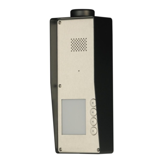
- Page 1 SOLO–NX COMPACT GSM DOOR ENTRY UNIT WITH 1, 2 or 4 CALL BUTTONS INSTALLATION MANUAL Version: Solo-NX EXT - Installation-Manual_V3_0-04102016.doc Valid from SW release: “SOLO_EF_B_ON_PCK_20160822_v_3_2_4”.
-
Page 2: Table Of Contents
SOLO-NX INSTALLATION MANUAL Contents FOR YOUR SAFETY ............................. 4 INTRODUCTION ..............................4 FEATURES AND APPLICATIONS ........................4 START UP ................................5 LED DISPLAY ................................ 6 CLEAR ALL PROGRAMMED DATA FROM SOLO-NX ................6 CONNECTION DIAGRAM ..........................7 PROGRAMMING SOLO-NX ..........................7 THE SOLO-NX PARAMETERS .......................... - Page 3 SOLO-NX INSTALLATION MANUAL 10.22 STATE OF THE CREDIT FOR THE PREPAID CARD ....................30 10.23 STATE OF THE OUTPUTS (PORC) ..........................30 10.24 MANUAL GSM MODULE RESTART (MRES) ......................30 10.25 RECEIVE STATUS OF INPUTS (INS) ..........................30 10.26 RECEIVE SOLO-NX LOG ............................... 30 CHANGING PARAMETERS USING THE SMS COMMANDS ..............
-
Page 4: For Your Safety
SOLO-NX INSTALLATION MANUAL FOR YOUR SAFETY Read these simple guidelines. Not following them may be dangerous or illegal. Read the complete user guide for further information. SWITCH ON SAFELY Do not switch the unit on when use of wireless phone is prohibited or when it may cause interference or danger. -
Page 5: Start Up
SOLO-NX INSTALLATION MANUAL START UP USE A MICRO SIM CARD (micro-SIM, see the picture) VERY IMPORTANT WITH MEMORY FOR UP TO 250 CONTACTS! Insert SIM card to be used for SOLO-NX in your personal mobile phone. ERASE THE PIN CODE! IMPORTANT ... -
Page 6: Led Display
SOLO-NX INSTALLATION MANUAL LED DISPLAY BLUE LED (LED1) Indicates the level of the GSM signal from 1 to 5 LED flashes (1 is weak signal, 5 is excellent signal) RED LED (LED2) When LED 2 is ON the unit has a problem with a GSM network connection or the GSM part of the unit is out of order. -
Page 7: Connection Diagram
SOLO-NX INSTALLATION MANUAL CONNECTION DIAGRAM Before connection the SOLO-NX please take a look at connection diagram. Figure 1: SOLO-NX Connection diagram *Do not use the Power out (12V AUX) for electric lock driving! You can use it to power external sensors: Short-term current load (up to 1 minute) - up to 500mA;... -
Page 8: The Solo-Nx Parameters
SOLO-NX INSTALLATION MANUAL THE SOLO-NX PARAMETERS To support versatile functionality of SOLO-NX different parameters are used. The parameters are divided in logical sections and are described in the following chapters. 9.1 ALARM SUPPORT Alarm reporting is supported by group of different parameters. First section is used to define the relations needed for alarm to be trigged. -
Page 9: Table 1: In, Id And Dd Parameters
SOLO-NX INSTALLATION MANUAL 9.1.1.4 Table of parameters Name Comment Mode of operation for input 1 Mode of operation for input 2 Input time integration delay on input 1 Input time integration delay on input 2 Time delay for alarm reporting on input 1 Time delay for alarm reporting on input 2 Table 1: IN, ID and DD parameters Example:... -
Page 10: Table 3: Remote Alarm Reporting Parameters
SOLO-NX INSTALLATION MANUAL 9.1.2.3 LOT parameter LOT parameter is used to define the time control for voice calls. The start of voice connection starts the LOT timer. If the voice connection is still ON when the LOT timer expires SOLO-NX disconnects voice connection. -
Page 11: Output Management
SOLO-NX INSTALLATION MANUAL 9.1.3 CONTROLING OUTPUTS WITH DTMF SOLO-NX can control the outputs with the use of DTMF. This is very useful function in the intercom application. To control the outputs the user must press the combination of 2 digits. First digit is used to select the output (1 to 2), the second digit is used to activate (1) or deactivate (0) the output. -
Page 12: Table 6: Output Management Parameters
SOLO-NX INSTALLATION MANUAL 9.2.2 OD parameter OD parameter is used to link the alarm event directly to output. 9.2.3 OP1, OP2 parameters Parameters are used to invert the polarity of the outputs. 0 – normal 1 – inverted 9.2.4 Table of parameters Name... -
Page 13: Security Level - Sl
SOLO-NX INSTALLATION MANUAL 9.3 SECURITY LEVEL - SL SL parameter from 0 to 5 defines which telephone number stored in the phone book from TN1 – TN5 can enter into programming and remote control of the SOLO-NX (dialing the SOLO-NX phone number or sending the SMS). -
Page 14: Table 10: Prepaid Card Validity Parameters
SOLO-NX INSTALLATION MANUAL 9.4.1 Programming prepaid card credit and validity string To be able to support credit and time validity checking different parameters are used. 9.4.1.1 LCV and SCV parameter LCV is used to set the limit for low credit event. If the credit on prepaid SIM cards falls below this limit SMS is send. -
Page 15: Set-Up Parameters
SOLO-NX INSTALLATION MANUAL Example: Direct programming on the SIM card SOLO-NX PROGRAMMING TABLE Name Number Description *448# Simobil 4916 TIM Italy Vodafone Italy Low credit message will be send bellow 4 Table 11: Credit example Remote programming by SMS ;CC1=*448#;CC2=4916;CC3=404;LCV=4;... - Page 16 SOLO-NX INSTALLATION MANUAL 9.5.5 TST parameter A test SMS is sent periodically. SOLO-NX can send the test message in the interval ranging from 1 hour to 240 hours. Example: To send test SMS TST value is set to 12, the numbers linked to “LN5” receive a test message every 12 hours.
-
Page 17: Table 12: Set-Up Parameters
SOLO-NX INSTALLATION MANUAL 9.5.10 MUT parameter MUT parameter enables you mutate the speaker sound while initiating voice connection. 9.5.11 ARST parameter ARST parameter defines periodic of auto restart time (in hours) of the SOLO-NX device. 9.5.12 ADF parameter Parameter is used to define voice refresh function, to prevent blocking of SIM in some networks. 9.5.13 LNG parameter LNG parameter switches between the preprogrammed languages:... -
Page 18: Sms Messages Editor
SOLO-NX INSTALLATION MANUAL Example: Direct programming on the SIM card SOLO-NX PROGRAMMING TABLE Name Number Description Hidden telephone number of the SOLO-NX device 29340 Manual fixing of the GSM provider (Simobil) Switch on Italian language Microphone volume level Speaker volume level 24 hours periodic test SMS Mute buzzer Input 2 is used as cancel button... -
Page 19: Gsm Intercom
SOLO-NX INSTALLATION MANUAL Example: Direct programming on the SIM card SOLO-NX PROGRAMMING TABLE Name Number Description #0House Location definition #1Kitchen Alarm input is from the kitchen Table 15: Message parameters example. Remote programming by SMS ;#0HOUSE=1;#1KITCHEN=1; 9.7 GSM INTERCOM Intercom functionality is supported by a set of parameters, used to tweak the functionality to each user needs. - Page 20 SOLO-NX INSTALLATION MANUAL 9.7.2 RTNx parameter Parameter defines the ring time time-out. RTNx timer is started when the call button is pressed. If the RTNx timer expires before the GSM voice connection is established then SOLO-NX device calls the next number in XTN1-XTN5 call list. 9.7.3 DTMF auto dial functionality This function is used to provide a support for SOLO-NX device to be able select extended numbers...
-
Page 21: Table 16: Intercom Parameters
SOLO-NX INSTALLATION MANUAL Name Comment RTNB Button 2, time out control for voice connection. SDNB Button 2, DTMF number to send. SDDB Button 2, delay for DTMF number to send. TZSB Button 2, time zone start period. TZEB Button 2, time zone end period. CTN1 Button 3, Telephone number 1. -
Page 22: Caller Id Recognition - Clip
SOLO-NX INSTALLATION MANUAL 9.8 CALLER ID RECOGNITION - CLIP CLIP is used to provide the “free of charge” options to control the outputs. 9.8.1 CLPEN parameter Parameter used to enable CLIP functionality. 9.8.2 CLPOU parameter Parameter used to choose which output will be controlled by the CLIP functionality. 9.8.3 CLPI parameter This parameter, if set, is a precondition for CLIP function to control the output. -
Page 23: Direct Access By Entering Pin Access Code
SOLO-NX INSTALLATION MANUAL 9.9 DIRECT ACCESS BY ENTERING PIN ACCESS CODE On SOLO-NX PCB there is a Wiegand input connector, where you can connect any Wiegand operated Keypad / Card reader. The user may control the predefined outputs by entering PIN access codes (up to 1000) and SPIN temporary access codes (up to 100). -
Page 24: Direct Access By Entering Temporary Access Codes - Spin - Via Illuminated Keypad
SOLO-NX INSTALLATION MANUAL 9.10 DIRECT ACCESS BY ENTERING TEMPORARY ACCESS CODES – SPIN - VIA ILLUMINATED KEYPAD The user may control the relay output by entering up to 100 temporary SPIN access codes which can be determined how many times they will be used. SPIN access code from SPIN1 to SPIN100 will activate the relay output. -
Page 25: Event Logging
SOLO-NX INSTALLATION MANUAL 9.11 EVENT LOGGING SOLO-NX device support logging of specific events. SOLO-NX logs CLIP event and alarm input events. Log event consist of event type, time and telephone number or input number. Up to 20.000 Log events can be stored. 9.11.1 LOGN parameter Parameter is used for defining the number of events printed out on PLOG request. -
Page 26: Special Sms Commands
SOLO-NX INSTALLATION MANUAL 9.12 SPECIAL SMS COMMANDS These commands can only be issued only over SMS message, and are used to control some special functions of SOLO-NX device. 9.12.1 ORC command Command is used to control outputs directly via SMS message 9.12.2 SDCLR command To clear all data on SIM card SDCLR command is used. -
Page 27: Print-Out Of The Parameters
SOLO-NX INSTALLATION MANUAL 10 PRINT-OUT OF THE PARAMETERS The user can check the settings of ALL parameters on the SOLO-NX. 10.1 RECEIVE ALL PARAMETERS (PALL) By sending this command to SOLO-NX you receive SMS messages with all parameters that are currently programmed in the unit: ;PALL;... -
Page 28: Receive Output Filter Value (Pod)
SOLO-NX INSTALLATION MANUAL 10.8 RECEIVE OUTPUT FILTER VALUE (POD) By sending this command to SOLO-NX you receive SMS message with all currently programmed direct output links (OD1 – OD5): ;POD; 10.9 RECEIVE DELAY BEFORE DIAL VALUE (PDD) By sending this command to SOLO-NX you receive SMS message with all currently programmed Input filters (DD1 –... -
Page 29: Receive Intercom Button 1 Paramaters (Pdea)
SOLO-NX INSTALLATION MANUAL User can use ;PCLP=x,y; to limit the number of CLIP numbers to be printed. x = start number NOTE y = end number Example ;PCLP=1,30; Prints first 30 CLIP numbers 10.16 RECEIVE INTERCOM BUTTON 1 PARAMATERS (PDEA) By sending this command to SOLO-NX you receive SMS message with all currently programmed button 1 group parameters (ATN1, ATN2, ATN3, ATN4, ATN5, RTNA, SDNA, SDDA, TZSA, TZEA):... -
Page 30: Receive Spin Access Codes Parameters (Pspin)
SOLO-NX INSTALLATION MANUAL 10.21 RECEIVE SPIN ACCESS CODES PARAMETERS (PSPIN) By sending this command to the device you receive SMS message with all currently programmed SPIN parameters: ;PSPIN; User can use ;PSPIN=x,y; to limit the number of SPIN numbers to be printed. x = start number NOTE y = end number... -
Page 31: Changing Parameters Using The Sms Commands
SOLO-NX INSTALLATION MANUAL 11 CHANGING PARAMETERS USING THE SMS COMMANDS All programming parameters for SOLO-NX can also be sent by SMS command. Each SMS command should start and stop with semicolon. If the confirmation SMS is needed, put “+” at the beginning of the command SMS. -
Page 32: Default Settings On Solo-Nx
SOLO-NX INSTALLATION MANUAL 12 DEFAULT SETTINGS ON SOLO-NX SOLO-NX PROGRAMMING TABLE Name Default Value Short Description Telephone number 1 Empty Telephone number 1 Empty Empty Telephone number 2 Empty Telephone number 3 Empty Telephone number 4 Input 1 control Input 2 control Output 1 mode Output 2 mode Input 1 direct output link... - Page 33 SOLO-NX INSTALLATION MANUAL SOLO-NX PROGRAMMING TABLE Name Default Value Short Description Speaker volume setting (0 - 20) Low credit value Language selection Connection time out value LOGN Number of log events for printing out LOGI Log interface Automatic log clear Auto dial functionality (Call TN1) ARST Automatic reset timeout...
-
Page 34: Table 28: Solo-Nx Default Settings
SOLO-NX INSTALLATION MANUAL SOLO-NX PROGRAMMING TABLE Name Default Value Short Description CTN2 Empty Button 3, Telephone number 2 CTN3 Empty Button 3, Telephone number 3 CTN4 Empty Button 3, Telephone number 4 CTN5 Empty Button 3, Telephone number 5 RTNC Ring time, Button 3 SDNC DTMF number to send... -
Page 35: Parameters Print-Out Commands
SOLO-NX INSTALLATION MANUAL 13 PARAMETERS PRINT-OUT COMMANDS SOLO-NX PROGRAMMING TABLE Name Short Description Prints all parameters available on SOLO-NX. PALL Prints SW version of SOLO-NX. Prints GSM network signal quality of SOLO-NX. Prints TNx numbers. Prints LNx links. Prints INx parameters. Prints IDx parameters. -
Page 36: Technical Specifications
Y (max. *100 mA) 12,0 – 20,0 V AC or 12,0 – 24,0 V DC Power Supply input Anti-tamper protection optional 15 CONTACTS MARS COMMERCE d.o.o. MIRKA VADNOVA 19 4000 KRANJ SLOVENIA TEL: 00 386 4 280 74 00 E-MAIL: info@mars-commerce.si WEB SITE: www.mars-commerce.com...
Need help?
Do you have a question about the SOLO–NX EXT and is the answer not in the manual?
Questions and answers