Table of Contents
Advertisement
Quick Links
This Quick Reference Guide provides all the steps necessary to install the SSA-4012-
xx. The SSA-4012 is a 6 x 12 audio matrix switcher and controller in a 1U rack-
mountable design.
Box Contents
(1) SSA-4012-xx unit
(1) Installation Kit (075-0144-xx)
(2) 1U Rack Mounting Brackets (071-0603-xx)
(4) Phillips Screws for Brackets (M3 x 8MM Flat) (039-0017-xx)
(2) 6-Pin Screw Down Plug in Connector (028-9352-xx)
(1) Power cord C13
(6 feet) (N. America) (064-0079-xx) or appropriate international power cord
(1) Quick Reference Guide (this document)
Required System Component
(1) Savant Smart Host or Savant Pro Host
Specifications
Environmental
Environmental
Temperature
Humidity
Cooling
Maximum BTUs
Dimensions and Weight
Dimensions and Weight
Height
Width
Depth
Weight
Rack Space
Power
Power
Input Power
Nominal Power
Maximum Power
Stereo Preamp Parameters
Stereo Preamp Parameters
Total Harmonic Distortion+Noise
(THD+N)
Dynamic Range
Signal-to-Noise Ratio (SNR)
Frequency Response
Output Impedance
Crosstalk
Supported Sample Rates
Compliance
Compliance
Safety and Emissions
RoHS
Minimum Support Release
Minimum Support Release
Savant OS
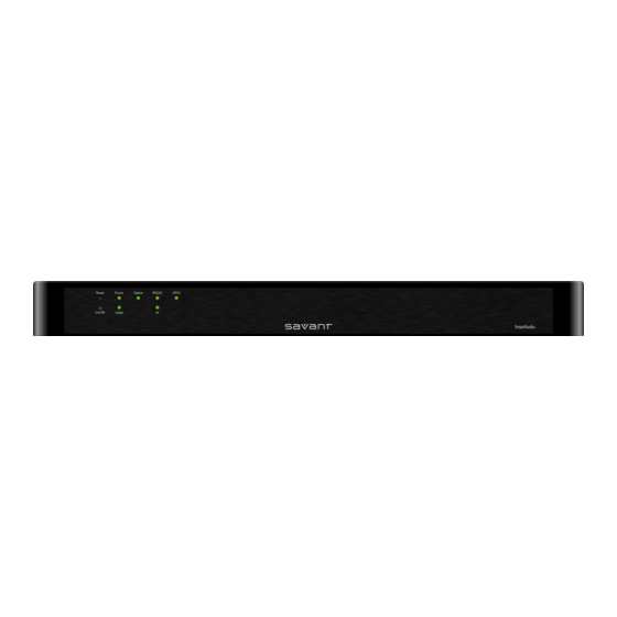
Front Panel
Reset button
Resets Static IP address. Insert pin into hole for 5 seconds
1
(hole)
to reset.
Green indicates the system has adequate power and is
operating normally.
Power Bi-color
2
Red indicates the system is in standby mode. In standby
LED
most of the Controller circuitry is powered down.
Off indicates that the system is getting no power.
SSA-4012-00 | 009-1201-01 | 140707
SmartAudio 6 x 12 Audio Matrix
Quick Reference Guide
32° to 104° F (0° to 40° C)
10% to 90% Relative Humidity (non-
condensing)
3 cubic feet per minute (CFM) recommended.
61 BTUs per hour
1.71 in (4.34 cm)
17.30 in (43.94 cm)
8.69 in (22.08 cm)
Net: 5.25 lb (2.38 kg)
Shipping: 7.8 lb (3.54 kg)
1U
100-240V AC, 50/60 Hz, (1.8 Amp maximum)
12 watt
18 watt
<0.005%, 20Hz - 20KHz, -100dB@1kHz
115dB
>105dB
20Hz - 20kHz +0dB +/-0.1dB
50 ohms
<-80dB
44.1 kHz/48 kHz/96 kHz/192 kHz at 16-bit or
24-bit resolution
FCC Part 15 | S Mark | CE Mark | C-Tick
Compliant
da Vinci 6.0.1
Savant Confidential and Proprietary
(SSA-4012)
Status Bi-color
3
LED
RS-232 LED
4
5
GPIO LED
On/Off button
6
(hole)
7
HDMI LED
8
IR LED
Rear Panel
1
Ethernet
2
RS-232/422/485
4
GPIO Input
5
GPIO Output
4
Host HDMI
5
Stereo In
6
Stereo Out
7
Fuse
8
Link/Activity LED
9
Ethernet Speed LED
10
IR
11
Digital Audio In
12
I/O (On/Off switch)
13
Input Power
Scan this QR code for additional
product information.
Green indicates the Host has established communications
with the embedded system.
Green flashing indicates the embedded system is ready
(running with DHCP IP address), but the Host has not
established communications with the embedded system.
Off indicates the embedded processor is resetting or is
powered up; and is booting the embedded firmware.
Red indicates the Host has determined the firmware needs
to be updated, but a problem occurred during the process
that will initiate a reset.
Red flashing indicates the embedded firmware is running,
but has not received a DHCP IP Address.
Amber indicates the Host is currently updating the
embedded firmware.
Amber flashing indicates the embedded system has a valid
link-local IP Address and is waiting to connect to the Host.
Hardware Failure
If the Controller has a hardware failure, the Status LED
indication will be interrupted every 3 seconds with a solid
red indication. For example, if the LED is flashing green
when a hardware failure occurs, the LED will flash green,
solid red, etc in 3 second intervals.
Green indicates RS-232 serial port data activity.
Off indicates no RS-232 serial port activity.
Green indicates GPIO port signal activity.
Off indicates no GPIO port activity.
Insert pin into hole for about 5 seconds to place in standby
mode. The Power LED turns red. Insert the pin again for
about 1 second to take system out of standby mode. The I/O
power switch on the back of Controller must be On (I) to
enable this function. To turn the power off for the entire
system, use the switch on the rear panel.
Green indicates the external host is connected to the
Host HDMI port.
Off indicates the external host is not connected to the
Host HDMI port.
Green indicates IR port signal activity.
Off indicates no IR port activity.
8-pin RJ-45 10/100 Base-T, auto-negotiating port with Link/
Activity LEDs:
See items 8 and 9 for LED operation.
8-pin RJ-45 female: Used to transmit and receive serial
binary data from devices.
Ports 1 & 2 support CTS/RTS.
When configured as an input, the port detects a voltage
present and can safely detect the presence of a voltage of
0-30V DC with a threshold of approximately 2.4V DC.
When configured as an output, the port outputs a voltage
below 12V DC 150mA. Combined maximum current for all
GPIO outputs is 550mA and will shut down if an over-current
condition is detected.
19-pin type A HDMI female digital video/audio input:
Supports HDMI, DVI/D (requires adapter-not included)
Limited to 185 MHz pixel clock. Used for receiving up to 4
PCM streams (iTunes®) from a Pro Host. This is not
available on the Smart Host.
RCA line-level analog audio inputs (4 Right & 4 Left)
RCA line-level analog audio outputs (12 Right & 12 Left)
100-240V, 2.5A—Fast acting fuse. This is field-replaceable.
Green indicates an Ethernet link has been established.
Green Flashing indicates Ethernet activity.
Off indicates an Ethernet link has not been established.
Yellow indicates an Ethernet connection speed of 100 Mbps.
Off indicates an Ethernet connection speed of 10 Mbps.
6-Pin Screw Down Plug in Connector (3.81 mm): (5V tolerant
only)
Sends IR signals to control devices with an IR input or IR
receiver via an IR flasher.
See
for important precautions regarding IR
functionality before making any connections.
TosLink (Optical) digital audio inputs. (2)
On/Off switch
I (On): Powers On the controller.
O (Off): Powers Off the controller.
100-240V AC, 50/60 Hz, 1.8 Amp
1 of 2
Advertisement
Table of Contents

Related Manuals for Savant SSA-4012-00


Summary of Contents for Savant SSA-4012-00
- Page 1 For example, if the LED is flashing green when a hardware failure occurs, the LED will flash green, (1) Savant Smart Host or Savant Pro Host solid red, etc in 3 second intervals. Green indicates RS-232 serial port data activity.
- Page 2 Connect all Savant devices to the same local area network (LAN), virtual local area network (VLAN), or subnet as the host. Savant recommends not implementing any type of traffic or packet shaping in your network topology for the Savant devices as this may interfere with performance.
Need help?
Do you have a question about the SSA-4012-00 and is the answer not in the manual?
Questions and answers