Table of Contents
Advertisement
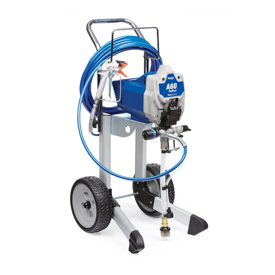
Operation, Parts
Magnum Pro Plus
Electric Airless Sprayers
Not approved for use in explosive atmospheres or hazardous locations.
For portable airless spraying of architectural paints and coatings.
Models: A60 Pro Plus & Pro Plus A80
3000 psi (207 bar, 20.7 MPa) Maximum Working Pressure
See page 3 for additional model information.
Important Safety Instructions
Read all warnings and instructions in this manual and related manuals.
Be familiar with the controls and the proper usage of the equipment.
Save these instructions.
Related Manuals
Gun – 312830 (SG3)
Use only genuine Graco replacement parts.
The use of non-Graco replacement parts may void warranty.
Pump – 3A3172
3A3240C
EN
ti28036a
Advertisement
Table of Contents

Related Manuals for Graco Magnum Pro Plus Series


Summary of Contents for Graco Magnum Pro Plus Series
- Page 1 Be familiar with the controls and the proper usage of the equipment. Save these instructions. Related Manuals Gun – 312830 (SG3) Pump – 3A3172 ti28036a Use only genuine Graco replacement parts. The use of non-Graco replacement parts may void warranty.
-
Page 2: Table Of Contents
Graco Standard Warranty ........ -
Page 3: Models
Models Models Model Series Cart A60 Pro Plus 17H224 Schuko Pro Plus A80 17H215 3A3240C... -
Page 4: Warnings
Warnings Warnings The following warnings are for the setup, use, grounding, maintenance, and repair of this equipment. The exclamation point symbol alerts you to a general warning and the hazard symbols refer to procedure-specific risks. When these symbols appear in the body of this manual or on warning labels, refer back to these Warnings. - Page 5 Use Graco conductive or grounded high-pressure airless paint sprayer hoses. •...
- Page 6 • Check hoses and parts for signs of damage. Replace any damaged hoses or parts. • This system is capable of producing 3000 psi. Use Graco replacement parts or accessories that are rated a minimum of 3000 psi. • Always engage the trigger lock when not spraying. Verify the trigger lock is functioning properly.
- Page 7 Warnings PRESSURIZED ALUMINUM PARTS HAZARD Use of fluids that are incompatible with aluminum in pressurized equipment can cause serious chemical reaction and equipment rupture. Failure to follow this warning can result in death, serious injury, or property damage. • Do not use 1,1,1-trichloroethane, methylene chloride, other halogenated hydrocarbon solvents or fluids containing such solvents.
-
Page 8: Know Your Sprayer
Know Your Sprayer Know Your Sprayer ti27117a Pump Fluid Outlet Fitting (airless PushPrime™ Button hose connection) Prime/Spray Valve Airless Hose Pressure Control Knob InstaClean™ Fluid Filter (inside fluid ON/OFF Switch outlet) Suction Tube Pail Hanger Drain Tube (with diffuser) Inlet Strainer Airless Spray Gun Power Cord Reversible Spray Tip... -
Page 9: Setup
When unpacking sprayer for the first time or after long term storage perform setup procedure. Assemble Your Sprayer Connect Graco airless hose to fluid outlet. Use wrench to tighten securely. ti25197a Turn pressure control knob all the way left (counter-clockwise) to lowest set- ting. -
Page 10: Start Up
Start Up Start Up to prevent the gun from being triggered accidentally. Pressure Relief Procedure Follow the Pressure Relief Procedure whenever you see this symbol. ti25198a Turn pressure control knob to lowest setting. This equipment stays pressurized until pressure is manually relieved. To help prevent serious injury from pressurized fluid, such as skin injection or splashed fluid, follow the Pressure Relief... - Page 11 Start Up Hold the gun firmly to a pail. Point gun into pail. Disengage the trigger lock and trigger the gun to relieve pressure. ti27466a Engage the trigger lock. If you suspect the spray tip or hose is clogged or that pressure has not been Turn Prime/Spray valve down to fully relieved: PRIME position.
- Page 12 Start Up 10. Turn ON/OFF switch to ON position. Wait to see paint coming out of drain tube. Turn ON/OFF switch to OFF position. NOTE: Some fluids may prime faster if the ON/OFF Switch is momentarily turned off so the pump can slow and stop.
-
Page 13: How To Spray
How to Spray How to Spray ti27143a Spray Tip Installation Spray tip must be pushed all the To prevent spray tip leaks make certain spray way into the tip guard. Turn spray tip tip and tip guard are installed properly. to push down. -
Page 14: Adjust Pressure Control
How to Spray Adjust Pressure Control The pressure control knob allows for infinite pressure adjustment. To reduce overspray, always start at the lowest pressure setting and increase pressure to the minimum setting that results in an acceptable spray pattern. 3000 psi 1500 psi 500 psi ti5597b... -
Page 15: Clear Tip Clog
How to Spray Triggering Gun • A smaller spray tip may be needed. • Material may need to be thinned. If Pull trigger after starting stroke. Release material needs to be thinned follow trigger before end of stroke. Gun must be manufacturer’s recommendations. -
Page 16: Cleanup
Cleanup Cleanup Cleaning the sprayer after each use results in a trouble free start up the next time the sprayer is used. ti27 7 124a Place empty waste and flushing fluid pails side by side. Cleaning from a Pail Place suction tube in flushing fluid. Use water for water based paint and mineral •... - Page 17 Cleanup Turn Prime/Spray valve down to 13. While continuing to trigger gun, quickly PRIME position. move gun to redirect spray into waste pail. Continue triggering gun into waste pail until flushing fluid dispensed from gun is relatively clear. ti27120a Turn ON/OFF switch to ON position. ti27151a 10.
- Page 18 Cleanup Cleanup with Power Flush Screw Power Flush attachment valve to garden hose. Close valve. Adapter (Water-based materials only) Power flushing is a faster method of cleanup. only used after spraying water-based coatings. Perform Pressure Relief Procedure, page 10. ti27 7155a Remove spray tip and tip guard assem- Turn on water.
- Page 19 Cleanup ™ Turn Prime/Spray valve horizontal Cleaning InstaClean to SPRAY position. Fluid Filter Turn ON/OFF switch to ON position. Continue to hold gun trigger until The InstaClean Fluid Filter prevents particles you see paint diluted with flushing from entering paint hose. After each use, fluid starting to come out of gun.
- Page 20 Cleanup Clean the Gun Remove spray tip and tip guard and clean with water or flushing fluid and a brush. Clean gun fluid filter with water or flushing fluid and a brush every time you flush the system. Replace gun filter if damaged.
-
Page 21: Storage
Storage Storage With proper storage, the sprayer will be ready Engage trigger lock. to use the next time it is needed. ti25196b Leave gun attached to hose. Remove tip and guard and clean with Short Term Storage water or flushing fluid and a brush. Wipe paint off outside of gun using a (up to 2 days) soft cloth moistened with water or flush-... - Page 22 Storage Turn Prime/Spray valve down to Leave gun attached to hose. PRIME position. Remove tip and guard and clean with water or flushing fluid and a brush. 10. Wipe paint off outside of gun using a soft cloth moistened with water or flush- ing fluid.
-
Page 23: Reference
Reference Reference Understanding Tip Number The last three digits of tip number (i.e.: Spray Tip Selection 221413) contain information about hole size and fan width on surface when gun is held 12 in. (30.5 cm) from surface being sprayed. Selecting Tip Size First digit when doubled Spray tips come in a variety of hole sizes for 413 tip has... -
Page 24: Cleaning Fluid Compatibility
Reference Cleaning Fluid Static Grounding Compatibility Instructions (Oil-Based materials) The equipment must be grounded to reduce the risk of static sparking and electric shock. An electric or static spark Oil- or Water-Based Materials can cause fumes to ignite or explode. An improper ground can cause electric shock. - Page 25 Reference Always ground a metal pail: connect a To maintain ground continuity when ground wire to the pail. Clamp one end to the sprayer is flushed or pressure is relieved: pail and the other end to a true earth ground hold metal part of spray gun firmly to the side such as a water pipe.
- Page 26 Reference Quick Reference Page 8 Name Description • Prime/Spray Valve In PRIME position directs fluid to drain tube. • In SPRAY position directs pressurized fluid to paint hose. • Automatically relieves system pressure in over- pressure situations. PushPrime Button Taps the inlet ball when pushed to loosen it. Pressure Control Knob Increases (clockwise) and decreases (counter-clockwise) fluid pressure in pump, hose,...
-
Page 27: Maintenance
• Purchase a pump repair kit and install according to instructions provided with kit, before your next job. • See Pump Assembly Parts, page 38 or consult a Graco/M authorized AGNUM retailer, distributor, or service center. ti27463a 3A3240C... - Page 28 Maintenance Inlet Valve Removal Slide pump assembly off the mounting pins. An integrated tool is included in the frame to remove the inlet valve assembly from the pump. If you suspect that the inlet valve is clogged or stuck, remove the valve assembly and clean or replace.
- Page 29 Maintenance Pump Installation Push on pump rod to slide pump assembly back on to mounting pins. Slide pump assembly onto the mounting Swing easy access door closed while pins. pushing the entire door towards the inlet end of the pump. ti27036a Move pump rod up or down until cap is level with the opening in the yoke.
-
Page 30: Troubleshooting
If not frozen, check for hardened paint in pump. If paint has hardened in pump. See page 27. If motor does not turn with pump removed, consult a Graco/ Magnum authorized retailer, distributor, or service center. Motor or control is damaged. - Page 31 Suction tube is leaking. Inspect suction tube connection for cracks or vacuum leaks. Outlet valve check ball is stuck. Unscrew outlet valve, remove, and clean assembly. Prime/Spray valve is worn or Take sprayer to Graco/MAGNUM obstructed with debris. authorized service center. 3A3240C...
- Page 32 Troubleshooting Problem Cause Solution Pump is primed, but can not achieve Spray tip may be partially clogged. Clear spray tip clog. See page 15. good spray pattern. Reversible spray tip is in UNCLOG Rotate arrow-shaped handle on spray position. tip so it points forward to SPRAY position.
- Page 33 Choose spray tip with narrower fan. Make sure gun is close enough to surface. Fan pattern varies dramatically while Pressure control switch is worn and Take sprayer to Graco/M AGNUM spraying. causing excessive pressure variation. authorized service center. Cannot trigger spray gun.
-
Page 34: A60: 17H224 Cart Sprayer Parts
A60: 17H224 Cart Sprayer Parts A60: 17H224 Cart Sprayer Parts Ref. Torque 30-35 in-lb (3.4 - 4.0 N•m) 110-120 in-lb (12 - 14 N•m) 45-55 ft-lb (5 - 6 N•m) See page 38. ti27244a 3A3240C... - Page 35 A60: 17H224 Cart Sprayer Parts 17H224 Cart Sprayer Parts List Part Description Ref. Qty. Part Description Ref. Qty. 17J058 LABEL, front 17F758 MOTOR, 230V includes 247340 HOSE, cpld, 1/4 in. x 50 1a, 22 16X980 KIT, motor, fan 16W431 GUN, spray,SG3 17J863 KIT, gear and yoke 112612...
-
Page 36: A80: 17H215 Cart Sprayer Parts
A80: 17H215 Cart Sprayer Parts A80: 17H215 Cart Sprayer Parts Ref. Torque 30-35 in-lb (3.5 - 4.0 N•m) 110-120 in-lb (12 - 14 N•m) 13 56 10b 10 See page 38. ti27247a 3A3240C... - Page 37 A80: 17H215 Cart Sprayer Parts 17H215 Cart Sprayer Parts List Part Description Ref. Qty. Part Description Ref. Qty. 17J871 TUBE, suction, MOTOR, 230V includes assembly includes 26a, 1a, 22 44, 46, 47, 49, 50, 51, 17L083 Series A 52, 53 17F758 Series B 26a 17L281...
-
Page 38: Pump Assembly Parts
Pump Assembly Parts Pump Assembly Parts Ref. Torque 140-160 in-lb (16 - 18 N•m) 30-35 in-lb (3.4 - 4.0 N•m) 30-35 ft-lb (40 - 48 N•m) 220-250 in-lb (25 - 28 N•m) 320-380 in-lb (36 - 43 N•m) ti27261a ti27261 3A3240C... - Page 39 Pump Assembly Parts Pump Parts List Part Description Ref. Qty. Part Description Ref. Qty. 120776 PACKING, O-ring 17G447 HOUSING, pump 24Y327 KIT, repair outlet 17D364 GUIDE, ball includes 12, 13 128336 SPRING, compression 17J880 KIT, outlet valve repair 105445 BALL, 0.5 in. 117501 SCREW, mach, slot includes 42...
-
Page 40: Wiring Diagram
Wiring Diagram Wiring Diagram 230V ti27485a 3A3240C... -
Page 41: Technical Specifications
Technical Specifications Technical Specifications Metric Sprayer Maximum fluid working pressure. 3000 psi 207 bar, 20.7 MPa Maximum Delivery 17H224 0.38 gpm 1.4 lpm 17H215 0.47 gpm 1.8 lpm Maximum Tip Size 17H224 0.019 in. 0.048 mm 17H215 0.021 in. 0.053 mm Fluid Outlet npsm 1/4 in. - Page 42 Technical Specifications Metric Notes * Startup pressures and displacement per cycle may vary based on suction condition, discharge head, air pressure, and fluid type. ** Sound pressure measured 3 feet (1 meter) from equipment while spraying. Sound power measured per ISO-9614. When pump is stored with non-freezing fluid.
-
Page 43: Graco Standard Warranty
Graco’s written recommendations. This warranty does not cover, and Graco shall not be liable for general wear and tear, or any malfunction, damage or wear caused by faulty installation, misapplication, abrasion, corrosion, inadequate or improper maintenance, negligence, accident, tampering, or substitution of non-Graco component parts. -
Page 44: Graco Information
For the latest information about Graco products, visit www.graco.com. For patent information, see www.graco.com/patents. TO PLACE AN ORDER, contact your Graco distributor or call 1-800-690-2894 to identify the nearest distributor. All written and visual data contained in this document reflects the latest product information available at the time of publication.
Need help?
Do you have a question about the Magnum Pro Plus Series and is the answer not in the manual?
Questions and answers