Table of Contents
Advertisement
Quick Links
Repair Kit Instructions
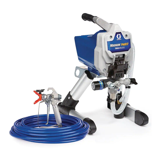
Repair Kits for
Magnum ProX & GX Sprayers
Use these instructions when repairing the ProX or GX sprayers.
IMPORTANT SAFETY INSTRUCTIONS
Read all warnings and instructions in the repair kit instructions and in the Owners/Operation manual for the
sprayer.
Contents
Section
Description
Front Cover Replacement page 3
Motor Replacement page 3
Fan Replacement page 4
Pressure Control Replacement page 9
Pump Inlet Valve Replacement page 12
PushPrime Button Replacement page 12
Refer to the illustrations in this document and your
Owners/Operation manual for additional parts
information, wiring diagrams, and any additional
assembly torques that you may need.
Pressure Relief Procedure
Before servicing the sprayer, pump pressure must be
relieved.
SKIN INJECTION HAZARD: This sprayer builds up
an internal pressure of 3000 psi (20.7 MPa, 207
bar) during use. This equipment stays pressurized
until pressure is manually relieved. Follow this
Pressure Relief Procedure whenever you stop
spraying and before cleaning, checking, servicing,
or transporting equipment to prevent serious injury.
Kit #
17J866
17F756, 17F757, 17F758,
17K684, 17L083
16X980, 287770
17J863, 17J864, 17J869
17J867, 17J885
17J881, 17J927
17J925, 235014
17J880
17J876, 17J877, 17J924
17J878
17J873, 17L305
1. Turn ON/OFF switch to the OFF position.
2. Engage the trigger lock. Always engage the trigger
lock when sprayer is stopped to prevent the gun
from being triggered accidentally.
3. Turn pressure control to lowest setting.
4. Put drain tube into a pail and place Prime/Spray
valve in PRIME position (drain) to relieve pressure.
5. Hold the gun firmly to a pail. Point gun into pail. Dis-
engage the trigger lock and trigger the gun to
relieve pressure.
6. Engage the trigger lock.
7. If you suspect the spray tip or hose is clogged or
that pressure has not been fully relieved:
a. VERY SLOWLY loosen the spray tip guard
retaining nut or the hose end coupling to relieve
pressure gradually.
b. Loosen the nut or coupling completely.
c. Clear airless hose or spray tip obstruction.
3A3951A
EN
Advertisement
Table of Contents

Related Manuals for Graco Magnum ProX


Summary of Contents for Graco Magnum ProX
-
Page 1: Table Of Contents
Pump Inlet Valve Replacement page 12 17J876, 17J877, 17J924 PushPrime Button Replacement page 12 17J878 4 Accessories Magnum ProX Lacquer Conversion page 13 17J873, 17L305 Refer to the illustrations in this document and your 1. Turn ON/OFF switch to the OFF position. - Page 2 Drive Drive Drive Assembly Drawing Ref. Torque 140-160 in-lb (16 - 18 N•m) 30-35 in-lb (3.5 - 4.0 N•m) 110-120 in-lb (12 - 14 N•m) ti28539a Description Ref. Description Ref. 10b Wire cover Motor 10c Cable Machine screw (T-30 Torx) Gear and yoke Switch bracket Power cord...
-
Page 3: Front Cover Replacement
Drive Front Cover Replacement See Drive Assembly Drawing page 2 and your Own- ers/Operation manual for illustrations. Disassembly 1. Perform Pressure Relief Procedure, on page 1. 2. Unplug sprayer. Remove Motor Shield 3. Remove two machine screws (9) and motor shield (8). -
Page 4: Fan Replacement
Drive Motor Replacement 7. Install gear and yoke (2). See Gear & Yoke Replacement page 5. See Drive Assembly Drawing page 2 and your Own- 8. Install front cover see Front Cover Replacement ers/Operation manual for illustrations. page 3 assembly procedure. 9. -
Page 5: Gear & Yoke Replacement
Drive e. Position the push nut and socket at the end of e. Place a push nut (54b) on a 3/8” or 10mm the motor shaft. Use a small or light (8 oz./225g) socket. hammer to drive the push nut (54b) onto the Position the push nut and socket at the end of shaft. - Page 6 Drive Assembly 8. Remove yoke (D) with the two yoke guide rods (C) from the drive housing. 1. Use applicator brush to spread entire contents of 9. Remove gear (A) from drive housing. grease tube (included in kit) into gear teeth. Grease must be worked into roots of gear teeth to ensure long life.
-
Page 7: Control Control Board Replacement
Control Control Control Board Replacement 2. Reconnect the power cord connector(s) to the cor- rect leads on the control board (15). Refer to your Owners/Operation manual for wiring dia- 3. Connect appropriate control board (15) lead(s) to grams. the ON/OFF switch (17). 4. - Page 8 Pump Pump Pump Assembly Drawing Ref. Torque Ref. Torque Ref. Torque 140-160 in-lb (16 - 18 N•m) 30-35 in-lb (3.4 - 4.0 N•m) 320-380 in-lb (36 - 43 N•m) 270-330 in-lb (30 - 37 N•m) 220-250 in-lb (25 - 28 N•m) ti27488a1 Ref.
-
Page 9: Pressure Control Replacement
Pump Pressure Control Replacement Assembly 1. Examine pressure control (28) to verify that O-ring (28c) is on the pressure control (28). If O-ring is not Disassembly installed on pressure control, install O-ring. 1. Perform Pressure Relief Procedure, on page 1. 2. -
Page 10: Prime/Spray Valve And Knob Replacement
Pump Prime/Spray Valve and Knob 7. Slide pump assembly onto the mounting pins. Replacement Disassembly 1. Perform Pressure Relief Procedure, on page 1. 2. Unplug sprayer. 3. Turn knob (A) up to SPRAY position. 4. Remove pin (B) with pin punch and hammer. ti27036a 8. -
Page 11: Pump Pump Outlet Valve Replacement
Pump Assembly 13. Install pin (B) through hole in knob (A). Tap pin through knob with hammer. End of pin will be flush 7. Apply sealant (provided in kit) to valve threads. with top of hole in knob when correctly installed. Install valve stem assembly in pump manifold and torque. -
Page 12: Pump Inlet Valve Replacement
Pump Pump Inlet Valve Replacement d. Install ball (4) into ball guide (2). 2. Make certain O-ring (6a) is installed on inlet valve housing (6). Disassembly 3. Thread new inlet valve housing into pump housing 1. Perform Pressure Relief Procedure, on page 1. (1) and torque. -
Page 13: Accessories Magnum Prox Lacquer Conversion
Accessories Accessories Magnum ProX Lacquer To convert a sprayer to spray lacquer materials several O-rings, suction tube, and Prime/Spray (drain) valve Conversion must be replaced. 1. Perform Pressure Relief Procedure, on page 1. To spray lacquers with the ProX17, ProX19, ProLTS170 or ProLTS190 sprayers you must install a lacquer con- 2. - Page 14 This manual contains English. MM 3A3951 Graco Headquarters: Minneapolis/International Offices: Belgium, China, Japan, Korea GRACO INC. AND SUBSIDIARIES • P.O. BOX 1441 • MINNEAPOLIS MN 55440-1441 • USA Copyright 2016, Graco Inc. All Graco manufacturing locations are registered to ISO 9001.
Need help?
Do you have a question about the Magnum ProX and is the answer not in the manual?
Questions and answers