
Summary of Contents for Siemens RUGGEDCOM RSG2300
- Page 1 Preface Introduction Installing Device RUGGEDCOM RSG2300 Communication Ports Technical Specifications Dimension Drawings Installation Guide Certification 12/2015 RC1046-EN-09...
- Page 2 Warranty Siemens warrants this product for a period of five (5) years from the date of purchase, conditional upon the return to factory for maintenance during the warranty term. This product contains no user-serviceable parts. Attempted service by unauthorized personnel shall render all warranties null and void.
- Page 3 RUGGEDCOM RSG2300 Installation Guide Contacting Address Telephone E-mail Siemens Canada Ltd. Toll-free: 1 888 264 0006 ruggedcom.info.i-ia@siemens.com Industry Sector Tel: +1 905 856 5288 300 Applewood Crescent Fax: +1 905 856 1995 www.siemens.com/ruggedcom Concord, Ontario Canada, L4K 5C7...
- Page 4 RUGGEDCOM RSG2300 Installation Guide...
-
Page 5: Table Of Contents
RUGGEDCOM RSG2300 Installation Guide Table of Contents Table of Contents Preface ....................... Alerts ..............................vii Related Documents ..........................vii Accessing Documentation ........................viii Training ............................viii Customer Support ..........................viii Chapter 1 Introduction ......................1.1 Feature Highlights ........................1 1.2 Description ..........................2 Chapter 2 Installing Device .................... - Page 6 RUGGEDCOM RSG2300 Table of Contents Installation Guide 3.3.2 Removing an SFP Optical Port ..................23 3.4 GBIC Optic Ethernet Ports ......................24 3.4.1 Installing a GBIC Optical Port ................... 24 3.4.2 Removing a GBIC Optical Port ..................25 3.5 BNC Ports ..........................26 Chapter 4 Technical Specifications ..................
-
Page 7: Preface
Installation Guide Preface Preface This guide describes the RUGGEDCOM RSG2300. It describes the major features of the device, installation, commissioning and important technical specifications. It is intended for use by network technical support personnel who are responsible for the installation, commissioning and maintenance of the device. -
Page 8: Accessing Documentation
Siemens sales representative. Customer Support Customer support is available 24 hours, 7 days a week for all Siemens customers. For technical support or general information, contact Siemens Customer Support through any of the following methods: Online Visit http://www.siemens.com/automation/support-request... -
Page 9: Introduction
(SFP, GBIC, LC, SC) without loss of port density. The RUGGEDCOM RSG2300 is packaged in a rugged galvanized steel enclosure with industrial grade DIN, panel, or 48 cm (19 in) rack-mount mounting options. -
Page 10: Description
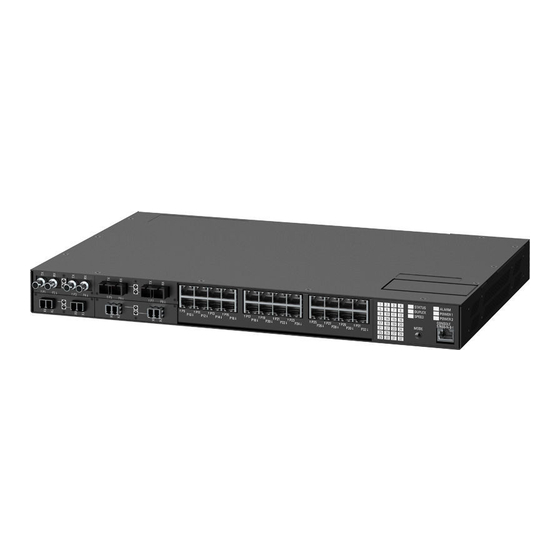
Section 1.2 Description The RUGGEDCOM RSG2300 features various ports, controls and indicator LEDs on the display panel for connecting, configuring and troubleshooting the device. The display panel can be located on the rear, front or top of the device, depending on the mounting configuration. - Page 11 RUGGEDCOM RSG2300 Chapter 1 Installation Guide Introduction Mode Color/State Description No link detected Duplex Green Full duplex mode Orange Half duplex mode No link detected Speed Green (Solid) 100 Mb/s Green (Blinking) 1000 Mb/s Orange (Solid) 10 Mb/s No link detected •...
- Page 12 RUGGEDCOM RSG2300 Chapter 1 Installation Guide Introduction Description...
-
Page 13: Installing Device
Mounting the Device The RUGGEDCOM RSG2300 is designed for maximum mounting and display flexibility. It can be equipped with connectors that allow it to be installed in a 48 cm (19 in) rack, 35 mm (1.4 in) DIN rail, or directly on a panel. -
Page 14: Mounting The Device To A Rack
Section 2.1.1 Mounting the Device to a Rack The RUGGEDCOM RSG2300 can be secured to a standard 48 cm (19 in) rack using separately purchased rack mount adapters. The adapters can be installed at the front or rear of the chassis. -
Page 15: Mounting The Device On A Din Rail
Mounting the Device on a DIN Rail For DIN rail installations, the RUGGEDCOM RSG2300 can be equipped with panel/DIN rail adapters pre-installed on each side of the chassis. The adapters allow the device to be slid onto a standard 35 mm (1.4 in) DIN rail. -
Page 16: Mounting The Device To A Panel
Section 2.1.3 Mounting the Device to a Panel For panel installations, the RUGGEDCOM RSG2300 can be equipped with panel/DIN rail adapters pre-installed on each side of the chassis. The adapters allow the device to be attached to a panel using screws. -
Page 17: Connecting Power
Section 2.2 Connecting Power The RUGGEDCOM RSG2300 supports a single or dual redundant AC and/or DC power supplies. The use of two power modules is recommended to provide redundancy and load balancing. The RUGGEDCOM RSG2300 can be equipped with either a screw-type or pluggable terminal block, which provides power to both power supplies. -
Page 18: Connecting Ac Power
Chapter 2 RUGGEDCOM RSG2300 Installing Device Installation Guide • Use only #16 gage copper wiring when connecting terminal blocks. • For 110/230 VAC rated equipment, an appropriately rated AC circuit breaker must be installed. • For 125/250 VDC rated equipment, an appropriately rated DC circuit breaker must be installed. -
Page 19: Connecting Dc Power
RUGGEDCOM RSG2300 Chapter 2 Installation Guide Installing Device Figure 5: Terminal Block Wiring 1. Screw-Type Terminal Block 2. Pluggable Terminal Block 3. Jumper 4. Positive/Live (+/L) Terminal 5. Negative/Neutral (-/N) Terminal (-/N) 6. Surge Ground Terminal 7. Chassis Ground Terminal Connect the negative wire from the power source to the negative/neutral (-/N) terminal on the terminal block. - Page 20 Chapter 2 RUGGEDCOM RSG2300 Installing Device Installation Guide NOTE The screw-type terminal block is installed using Phillips screws and compression plates, allowing either bare wire connections or crimped terminal lugs. Use #6 size ring lugs for secure, reliable screws, which must be removed to make connections.
-
Page 21: Wiring Examples
RUGGEDCOM RSG2300 Chapter 2 Installation Guide Installing Device Section 2.2.3 Wiring Examples The following illustrate how to connect power to single and dual power supplies. Figure 7: Single AC Power Supply Figure 8: Single DC Power Supply Wiring Examples... - Page 22 Chapter 2 RUGGEDCOM RSG2300 Installing Device Installation Guide Figure 9: Dual AC Power Supply Figure 10: Dual DC Power Supply Wiring Examples...
-
Page 23: Connecting The Failsafe Alarm Relay
Control of the failsafe relay output is configurable through ROS. One common application for this relay is to signal an alarm if a power failure occurs. For more information, refer to the ROS User Guide for the RUGGEDCOM RSG2300. The following shows the proper relay connections. -
Page 24: Grounding The Device
Section 2.4 Grounding the Device The RUGGEDCOM RSG2300 chassis ground terminal uses a #6-32 screw. It is recommended to terminate the ground connection with a #6 ring lug and torque it to 1.7 N·m (15 lbf·in). Figure 13: Chassis Ground Connection 1. -
Page 25: Cabling Recommendations
RUGGEDCOM RSG2300 Chapter 2 Installation Guide Installing Device RS232 Console Port Connect a PC or terminal directly to the RS232 console port to access the boot-time control and ROS interfaces. The console port provides access to ROS's console and Web interfaces. -
Page 26: Protection On Twisted-Pair Data Ports
Section 2.6.1 Protection On Twisted-Pair Data Ports Siemens does not recommend the use of copper cabling of any length for critical, real-time substation automation applications. All copper Ethernet ports on RUGGEDCOM products include transient suppression circuitry to protect against damage from electrical transients and conform with IEC 61850-3 and IEEE 1613 Class 1 standards. -
Page 27: Communication Ports
Installation Guide Communication Ports Communication Ports The RUGGEDCOM RSG2300 can be equipped with various types of communication ports to enhance its abilities and performance. Figure 15: Port Assignment Each type of module has a specific location in the RUGGEDCOM RSG2300 chassis: •... -
Page 28: Copper Ethernet Ports
Section 3.1 Copper Ethernet Ports The RUGGEDCOM RSG2300 supports several 10/100/1000Base-TX Ethernet ports that allow connection to standard Category 5 (CAT-5) unshielded twisted-pair (UTP) cables with either RJ45 male connectors. The RJ45 connectors are directly connected to the chassis ground on the device and can accept CAT-5 shielded twisted- pair (STP) cables. -
Page 29: Fiber Optic Ethernet Ports
RUGGEDCOM RSG2300 Chapter 3 Installation Guide Communication Ports Name Description 10/100Base-TX 1000Base-TX Reserved (Do BI_DC+ Transmit Data+ Not Connect) or Bi-Directional Pair C+ Reserved (Do BI_DC- Receive Data- Not Connect) or Bi-Directional Pair C- BI_DB- Transmit Data- or Bi-Directional Pair B-... -
Page 30: Sfp Optic Ethernet Ports
To install an SFP optical port, do the following: CAUTION! Electrical hazard – risk of damage to equipment. Use only components certified by Siemens with RUGGEDCOM products. Damage to the module and device may occur if compatibility and reliability have not been properly assessed. -
Page 31: Removing An Sfp Optical Port
RUGGEDCOM RSG2300 Chapter 3 Installation Guide Communication Ports Insert the port into the module and swing the bail-latch up to lock it in place. Figure 27: Installing an SFP Optical Port (Typical) 1. SFP Optical Port 2. Metal Bail-Latch Remove the dust cover from the port. -
Page 32: Gbic Optic Ethernet Ports
To install a GBIC optical port, do the following: CAUTION! Electrical hazard – risk of damage to equipment. Use only components certified by Siemens with RUGGEDCOM products. Damage to the module and device may occur if compatibility and reliability have not been properly assessed. -
Page 33: Removing A Gbic Optical Port
RUGGEDCOM RSG2300 Chapter 3 Installation Guide Communication Ports Figure 30: Installing a GBIC Optical Port 1. GBIC Optical Port Module 2. GBIC Optical Port 3. Locking Latch Release the latches and make sure the module is locked in place. Remove the dust cover from the port. -
Page 34: Bnc Ports
Inputs are controlled by RUGGEDCOM ROS and only one can be active at any time. For information about activating an input, refer to the RUGGEDCOM ROS User Guide for the RUGGEDCOM RSG2300. The color of the Sync LED on the front panel of the PTP module indicates the status of the incoming timing signal: •... - Page 35 RUGGEDCOM RSG2300 Chapter 3 Installation Guide Communication Ports • Red – Error • Off – No signal detected BNC Ports...
- Page 36 RUGGEDCOM RSG2300 Chapter 3 Installation Guide Communication Ports BNC Ports...
-
Page 37: Technical Specifications
RUGGEDCOM RSG2300 Chapter 4 Installation Guide Technical Specifications Technical Specifications The following sections provide important technical specifications related to the device and available modules: • Section 4.1, “Power Supply Specifications” • Section 4.2, “Failsafe Relay Specifications” • Section 4.3, “Supported Networking Standards”... -
Page 38: Supported Networking Standards
Chapter 4 RUGGEDCOM RSG2300 Technical Specifications Installation Guide Parameter Value (Resistive Load) Maximum Switching Capacity 150 W, 500 VA Section 4.3 Supported Networking Standards 1000 Mbps Standard 10 Mbps Ports 100 Mbps Ports Notes Ports IEEE 802.3 10BaseT/10BaseFL ü IEEE 802.3u 100BaseTX/100BaseFX ü... -
Page 39: Copper Gigabit Ethernet (1 Gbps) Port Specifications
NOTE • Maximum segment length is greatly dependent on factors such as fiber quality, and the number of patches and splices. Consult a Siemens sales associate when determining maximum segment distances. • All optical power numbers are listed as dBm averages. -
Page 40: 10Fl Ethernet Optical Specifications
Chapter 4 RUGGEDCOM RSG2300 Technical Specifications Installation Guide • Section 4.5.2, “Fast Ethernet (10/100 Mbps) Optical Specifications” • Section 4.5.3, “Gigabit Ethernet (1 Gbps) Optical Specifications” Section 4.5.1 10FL Ethernet Optical Specifications Power Connector Cable Tx min Tx max Distance Mode Tx λ... -
Page 41: Gigabit Ethernet (1 Gbps) Optical Specifications
All optical power numbers are listed as dBm averages. Typical distance. The maximum segment length is greatly dependent on factors such as fiber quality, and the number of patches and splices. Consult a Siemens sales associates when determining maximum segment distances. -
Page 42: Operating Environment
All optical power numbers are listed as dBm averages. Typical distance. The maximum segment length is greatly dependent on factors such as fiber quality, and the number of patches and splices. Consult a Siemens sales associates when determining maximum segment distances. -
Page 43: Dimension Drawings
RUGGEDCOM RSG2300 Chapter 5 Installation Guide Dimension Drawings Dimension Drawings NOTE All dimensions are in millimeters, unless otherwise stated. NOTE Dimensional tolerances are in accordance with ISO 2768-mK, unless otherwise stated. 438.15 Figure 33: Overall Dimensions... - Page 44 Chapter 5 RUGGEDCOM RSG2300 Dimension Drawings Installation Guide 32.64 21.08 11.68 479.29 461.01 4.57 Figure 34: Rack Mount Dimensions...
- Page 45 RUGGEDCOM RSG2300 Chapter 5 Installation Guide Dimension Drawings 486.4 476.3 10.4 11.7 Figure 35: Panel and DIN Rail Mount Dimensions...
- Page 46 RUGGEDCOM RSG2300 Chapter 5 Installation Guide Dimension Drawings...
-
Page 47: Certification
RUGGEDCOM RSG2300 Chapter 6 Installation Guide Certification Certification The RUGGEDCOM RSG2300 device has been thoroughly tested to guarantee its conformance with recognized standards and has received approval from recognized regulatory agencies. • Section 6.1, “Standards Compliance” • Section 6.2, “Agency Approvals”... -
Page 48: Emc And Environmental Type Tests
Chapter 6 RUGGEDCOM RSG2300 Certification Installation Guide Section 6.3 EMC and Environmental Type Tests The RUGGEDCOM RSG2300 has passed the following EMC and environmental tests. IEC 61850-3 EMC Type Tests Test Description Test Levels Severity Levels IEC 61000-4-2 Enclosure Contact... - Page 49 Only applicable to functional earth connections separated from the safety earth connection. IEEE 1613 EMC Immunity Type Tests NOTE The RUGGEDCOM RSG2300 meets Class 2 requirements for an all-fiber configuration and Class 1 requirements for copper ports. Description Test Levels...
- Page 50 Chapter 6 RUGGEDCOM RSG2300 Certification Installation Guide Environmental Type Tests Test Description Test Levels IEC 60068-2-1 Cold Temperature Test Ad -40 °C (-40 °F), 16 Hours IEC 60068-2-2 Dry Heat Test Bd 85 °C (185 °F), 16 Hours IEC 60068-2-30...
Need help?
Do you have a question about the RUGGEDCOM RSG2300 and is the answer not in the manual?
Questions and answers