Table of Contents
Advertisement
Quick Links
P . I.P . – EDCb
EDC
b
Programmable
Input Processor (P.I.P.)
© 1997 by Crown International, Inc., P.O. Box 1000, Elkhart, IN 46515-1000
U.S.A. Telephone: 219-294-8000. Fax: 219-294-8329. P.I.P. modules are
produced by the Professional Audio Division of Crown International, Inc.
Trademark Notice: Crown
registered trademarks of Crown International, Inc. Other trademarks are the
property of their respective owners.
Printed on
recycled paper.
C H - 2
PUSH
I N P U T
I N P U T
®
®
, Macro-Tech
, Com-Tech
C H - 1
PUSH
®
®
, IOC
and P.I.P.
3
GND
1
2
®
are
125511-1
11/97
Advertisement
Table of Contents

Subscribe to Our Youtube Channel
Related Manuals for Crown PIP-EDCB


Summary of Contents for Crown PIP-EDCB
- Page 1 P . I.P . – EDCb Programmable Input Processor (P.I.P.) © 1997 by Crown International, Inc., P.O. Box 1000, Elkhart, IN 46515-1000 U.S.A. Telephone: 219-294-8000. Fax: 219-294-8329. P.I.P. modules are produced by the Professional Audio Division of Crown International, Inc.
- Page 2 P .I.P .–EDCb Page 2...
-
Page 3: Feature Summary
P .I.P .–EDCb Programmable Input Processor (P.I.P.) 1 Welcome Thank you for purchasing the Crown P.I.P.-EDCb . P.I.P. modules are designed to quickly install in the back of many Crown amplifiers. P.I.P. stands for “Programmable In- put Processor. ” Their versatile... -
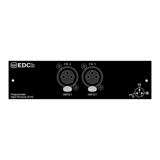
Page 4: Input Connectors
Fig. 2.1 P.I.P.-EDCb (Bottom View) 2 Facilities A. Input Connectors A balanced XLR connector is provided for input to each chan- nel. The pin assignments are labeled on the face of the P.I.P. Refer to your amplifier Owner’s Manual for wiring details. CAUTION: Input channel 2 should NOT be used in either mono mode, and its level con-... - Page 5 P .I.P .–EDCb maximum output voltage and can be used to protect loud- speakers and listeners. When turned to the maximum setting (fully clockwise), the compres- sor responds only to the channel’s IOC error signal. When set lower, the compres- sor responds to a maximum audio level (see Figure 3.4).
-
Page 6: Installation
3 Installation Before installing the P.I.P. mod- it should first be configured. ule, 3.1 P.I.P. Configuration 1. Set the corner frequency (–3 dB frequency) for each subsonic filter with DIP switches S1 and S2 (see Figure 3.2). Notice that the first six switch segments control the corner frequency. -
Page 7: Installation Procedures
P .I.P .–EDCb Macro-Tech 3600VZ and Max Sine Mark Wave RMS Voltage Fig. 3.4 Compressor Threshold Settings pot has a scale with ten marks (or settings) which correspond to the typical thresholds shown in Figure 3.4. 4. Move the P.I.P.’s tracking jumper (Z1) to the “ON”... - Page 8 (see Figure 3.5). 18 PIN (B) 20 PIN (A) PIP2 Amplifiers: (Requires a PIP2 input adaptor. Crown part number Q43528-1.) Connect the PIP2 input adapter to the two input cables of the amplifier (see Figure 3.6). Notice that the PIP2 input adapter should be positioned with the P.I.P.
- Page 9 Do not tamper with the circuitry. Circuit changes made by unau- thorized personnel, or unautho- rized circuit modifications are not allowed. Remember: Crown is not liable for any damage resulting from overdriving other components in your sound system. CAUTION: IF PHONE JACKS...
- Page 10 P .I.P .–EDCb Electronic image for this figure were not included due to quality considerations. Please refer to the printed documentation. Only one channel shown. Page 10...
- Page 11 P .I.P .–EDCb Electronic image for this figure were not included due to quality considerations. Please refer to the printed documentation. Notes: 1. All resistor values are in ohms, W, 1% unless otherwise specified. 2. All capacitor values are in micro-farads unless otherwise specified. Page 11...
-
Page 12: Specifications
Less than 0.01% THD at 1 kHz. Common Mode Rejection: Greater than 65 dB at 1 kHz. Crown Audio Division Technical Support Group Plant 2 SW, 1718 W. Mishawaka Rd., Elkhart, Indiana 46517 U.S.A. Phone: 800-342-6939 (North America, Puerto Rico and Virgin Islands) or 219-294-8200...
Need help?
Do you have a question about the PIP-EDCB and is the answer not in the manual?
Questions and answers