Crown IQ-PIP-USP2 Reference Manual
Ultra series
Hide thumbs
Also See for IQ-PIP-USP2:
- Reference manual (65 pages) ,
- Installation manual (12 pages) ,
- Specifications (2 pages)
Table of Contents
Advertisement
Quick Links
*
*
*
*
*
PIP-USP2
PIP-USP2
PIP-USP2
PIP-USP2
PIP-USP2
®
An IQ System
Programmable Input Processor with DSP and
Load Supervision for Crown
© 2002 by Crown Audio, Inc., P.O. Box 1000, Elkhart, IN 46515-1000 U.S.A.
Telephone: 574-294-8000. Fax: 574-294-8329. Trademark Notice: IQ2, SmartAmp,
PIP, and PIP2 are trademarks, and Com-Tech, Crown , IOC, IQ System, Macro-Tech
and ODEP are registered trademarks of Crown International. Other trademarks are
the property of their respective owners.
Obtaining Other Language Versions:
To obtain information in another language about the use of this product, please
contact your local Crown Distributor. If you need assistance locating your local
distributor, please contact Crown at 574-294-8200.
Note: The information provided in this manual was
deemed accurate as of the publication date. How-
ever, updates to this information may have occurred.
To obtain the latest version of this manual, please
visit the Crown website at www.crownaudio.com.
Printed on
recycled paper.
®
PIP2-Compatible Amplifiers
125981-4
2/02
Advertisement
Table of Contents

Related Manuals for Crown IQ-PIP-USP2


Summary of Contents for Crown IQ-PIP-USP2
- Page 1 Load Supervision for Crown PIP2-Compatible Amplifiers © 2002 by Crown Audio, Inc., P.O. Box 1000, Elkhart, IN 46515-1000 U.S.A. Telephone: 574-294-8000. Fax: 574-294-8329. Trademark Notice: IQ2, SmartAmp, PIP, and PIP2 are trademarks, and Com-Tech, Crown , IOC, IQ System, Macro-Tech and ODEP are registered trademarks of Crown International.
-
Page 2: Quick Install Procedure
Prepare the IQ-PIP-USP2: 1. Set the IQ address switch S1 (see Figures 2.1 and 3.1) on the IQ-PIP-USP2 to an unused IQ address. (Tip: Record the IQ address on the small field labeled “IQ ADDRESS” that is provided on the PIP panel.) 2. -
Page 3: Table Of Contents
3.2 Scaling Switch (S3) ... 1 0 3.3 Scaling Chart ... 1 0 3.4 Installing the IQ-PIP-USP2 ... 11 3.5 Crown Bus Wiring “Loops” from Output to Input 12 3.6 RJ-45 Mating Plug ... 12 3.7 RJ-45 Output to Barrier Block Input ... -
Page 4: Welcome
AUX input and output, and amplifiers.* It connects the amplifier Listen Bus, as well as a host of other to the Crown Bus of an IQ System, useful features similar to those in- allowing the amplifier to be controlled cluded with our other SmartAmp and monitored via IQ. -
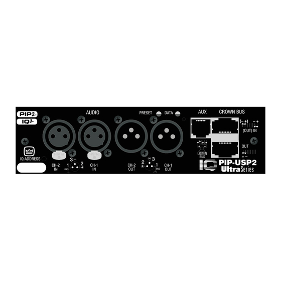
Page 5: Controls, Connectors & Indicators
2 Controls, Connectors & Indicators Figure 2.1 IQ-PIP-USP2 Controls, Connectors and Indicators Page 8 IQ-PIP-USP2 Reference Manual IQ-PIP-USP2 IQ-PIP-USP2 3 Installation Before beginning, please carefully note: CAUTION: STATIC ELECTRICITY MAY DAMAGE THE IQ-PIP-USP2 MODULE. Use caution when han- dling the unit. Carefully ground your- self BEFORE touching the IQ-PIP- USP2 module. -
Page 6: Prepare The Amplifier
+20 dBu. Figure 3.2 shows S3 set for +20 dBu. 6. Carefully ground yourself to the chassis of the amplifier before installing the IQ-PIP-USP2. It is a good idea to maintain ground contact between yourself and the amplifier while inserting the module into the amplifier. - Page 7 Wiring “Loops” from the Output to the Input of each IQ Component (for Hub-Style Crown Bus wiring, see Section 5.2.1). The following examples show how to connect the IQ-PIP-USP2 to other IQ components: Figure 3.7 RJ-45 Output to Barrier Block Input. Page 12...
-
Page 8: Adjust System Levels
Crown Bus wiring configuration, and can be used for both input and output when a “hub” style Crown Bus wir- ing configuration is implemented (see Section 5.2). Drop-out relays maintain loop integrity in the event... -
Page 9: Crown Bus Daisy Output Connector
6 of the RJ-11 connector (soft- An RJ-45 connector is provided for ware selectable). normal daisy wiring output to the 4.1.8 Crown Bus “Drop Out” next device on the loop in the Crown Relays Bus. “Drop out” relays are provided on 4.1.5 Balanced Audio Inputs... -
Page 10: Amplifier Control And Monitoring
IOC event, much stress.*** The Thermal Limiter Also, it can report IOC events to it’s feature of the IQ-PIP-USP2 can be AUX port. set to engage upon a pre-selected 4.3.3 Input Signal Level Monitor thermal level. -
Page 11: Error Reporting
Channel 1 and Channel 2 XLR inputs to drive the processing path for each chan- nel of the IQ-PIP-USP2. You can also route the output of either chan- nel to Channel 1 or Channel 2 ampli- fier inputs. -
Page 12: Programmable Filters
The range is from +16 dBu to DSP filters can be processed pre or –40 dBu. post crossover, depending upon which form the IQ-PIP-USP2 is con- Attack Time: Sets the attack time of figured in (see the IQ for Windows the compressor. The attack time is... -
Page 13: Signal Delay
* The low and high-pass equalization fil- ters can be cascaded to form unique signal delay. The range is 0 millisec- inter-order crossover-type filters. Page 24 IQ-PIP-USP2 Reference Manual IQ-PIP-USP2 IQ-PIP-USP2 onds to 500 milliseconds in 1 milli- second steps. -
Page 14: Output Trim Controls
Report to Aux: Enables any high/ such as would typically be desired low status condition to be reported when processing stereo signals. via the IQ-PIP-USP2 aux port output 4.5 Load Supervision (See Section 4.1.7). Test Indicator: This indicator lights The Load Supervision feature allows... -
Page 15: Iq Audio In Depth
Crown Bus loop having an IQ2-compatible IQ interface in order for the IQ System to control or monitor it. The Crown Bus is a serial communication loop designed to transmit IQ commands and data. As implemented in the IQ-PIP-USP2, it is a 20 milliamp current loop operat- ing at a BAUD rate of 38.4 K. -
Page 16: Hub" Style Crown Bus Wiring
IQ-PIP-USP2 STANDARD THRU-TYPE NETWORK CABLE (CAT.5) Figure 5.3 Example of “Hub” Style Crown Bus Wiring Arrangement 5.3 Using the AUX Connector The IQ System offers tremendous flexibility and the auxiliary feature connector provides a means of tap- ping into it. It can be used to turn... -
Page 17: Aux Input
“high” and will be communi- nally clamped to protect the internal cated to the Crown Bus where a host circuitry. Page 32 IQ-PIP-USP2 Reference Manual IQ-PIP-USP2 Figure 5.5... -
Page 18: Q-Factor Calculation
(1/K) –1 IQ-PIP-USP2 5.7 Load Supervision Applications The IQ-PIP-USP2 Load Supervision 5 Set the high limit at twice average and the low limit at one-fourth feature can be used to monitor the nominal.* amplifier load in real time with al- most any program material. -
Page 19: Typical Load
If the PRESET indicator does not flash the preset number when * If address “0” is selected, the IQ-PIP- USP2 will operate in stand-alone mode. In this mode, the Crown bus port is de- activated. IQ-PIP-USP2 Reference Manual selected, this indicates the preset has been modified by the user. -
Page 20: Iq Address Tables
0.775 V (0 weighted, 20 Hz to 20 kHz). dBu). Measurements were made at Frequency Response: ±0.5 dB from the output of the IQ-PIP-USP2 mod- 20 Hz to 20 kHz. ule, itself. Common Mode Rejection (CMR): Digital Signal Processor (DSP): 50 dB (typical). -
Page 21: Iq Address Switch (S1)
IQ-PIP-USP2 IQ-PIP-USP2 Figure 7.2 IQ Address Switch (S1) Settings from 84 through 167 Figure 7.1 IQ Address Switch (S1) Settings from 0 through 83 Page 40 Page 41 IQ-PIP-USP2 Reference Manual IQ-PIP-USP2 Reference Manual... -
Page 22: Using The Iq-Pip-Usp2 With The Iq-Pip-Usp2 Adapter
Crown PIP-compatible amplifiers (i.e., Macro-Tech Series, Com-Tech Studio Reference Series amplifiers) to access the power and versatility of the Crown IQ-PIP-USP2 module. The IQ-PIP-USP2 Adapter can be installed into the following Crown amplifier models: CT-200*, CT-400*, CT-800*, CT-1600*... -
Page 23: Signal Path" Tab Showing Peak Voltage And Average Power Limiters Disabled
Figure 8.1 "General" Tab showing Identification of IQ-PIP-USP2 Adapte Peak Voltage and Average Power Voltage Limiter Peak Voltage and Average Power Limiters are not available. Figure 8.2 “Signal Path” Tab showing Peak Voltage and Average Power Limiters Disabled Page 44... -
Page 24: Error Reporting" Tab Showing Fault And
Figure 8.5 “Error Reporting” Tab showing Fault and Load Error Reporting Disabled Load Supervision Load Supervision is not available. Figure 8.6 “Load Supervision” Tab showing Load Supervision Disabled Page 46 IQ-PIP-USP2 Reference Manual IQ-PIP-USP2 IQ-PIP-USP2 IQ-PIP-USP2 Reference Manual Page 47... -
Page 25: Crown Factory Service
8 Service and the defective unit to the Crown factory. 8.1 Worldwide Service For warranty service, we will pay for Service may be obtained from an ground shipping both ways in the authorized service center. (Contact United States. Contact Crown Fac-... - Page 26 ORIGINAL PURCHASER and ANY SUBSEQUENT OWNER of each NEW Crown product, for a period of three (3) years from the date of purchase by the original purchaser (the “warranty period”) that the new Crown product is free of defects in materials and workmanship.
- Page 27 ❏ ❏ ❏ ❏ ❏ VISA ❏ ❏ ❏ ❏ ❏ MasterCard ❏ ❏ ❏ ❏ ❏ C.O.D. Card Number:___________________________ Exp. Date: __________ Signature:____________________________ ENCLOSE THIS PORTION WITH THE UNIT. DO NOT MAIL SEPARATELY. ❏ ❏ ❏ ❏ ❏ P.O. for Crown Dealer...
Need help?
Do you have a question about the IQ-PIP-USP2 and is the answer not in the manual?
Questions and answers