Table of Contents
Advertisement
Quick Links
An IQ System
®
Programmable Input Processor
for Crown
®
P.I.P.
®
-compatible Power Amplifiers
© 1998 by Crown International, Inc., P.O. Box 1000, Elkhart, Indiana
46515-1000 U.S.A. Telephone: 219-294-8000. The IQ–P.I.P.–SMT is
produced by the Professional Audio Division of Crown International,
Inc. Trademark Notice: MPX-6
™
, SMX-6
™
, SmartAmp
™
and Macro
Reference
™
are trademarks and Amcron
®
, Crown
®
, IQ System
®
, IOC
®
,
ODEP
®
, Macro-Tech
®
, Com-Tech
®
and P.I.P.
®
are registered
trademarks of Crown International, Inc. Other trademarks are the
property of their respective owners.
Printed on
recycled paper.
126821-1
10/98
Advertisement
Table of Contents

Subscribe to Our Youtube Channel
Related Manuals for Crown IQ-P.I.P-SMT


Summary of Contents for Crown IQ-P.I.P-SMT
- Page 1 Crown ® P.I.P. ® -compatible Power Amplifiers © 1998 by Crown International, Inc., P.O. Box 1000, Elkhart, Indiana 46515-1000 U.S.A. Telephone: 219-294-8000. The IQ–P.I.P.–SMT is produced by the Professional Audio Division of Crown International, Inc. Trademark Notice: MPX-6 ™...
- Page 2 No person has the authority to enlarge, amend, or modify this Crown Warranty. This Crown Warranty is not extended by the length of time which you are deprived of the use of the new Crown product. Repairs and replacement parts provided under the terms of this Crown Warranty shall carry only the unexpired portion of this Crown Warranty.
- Page 3 No person has the authority to enlarge, amend, or modify this Crown Warranty. This Crown Warranty is not extended by the length of time which you are deprived of the use of the new Crown product. Repairs and replacement parts provided under the terms of this Crown Warranty shall carry only the unexpired portion of this Crown Warranty.
-
Page 4: Quick Install Procedure
Quick Install Procedure This procedure is provided for those who are already familiar with Crown’s IQ System and who would like to install the IQ–P.I.P.–SMT in the shortest time possible. Less experienced installers or those wishing a full explanation of the installation procedure are encouraged to go to Section 4 where the full installation procedure is described. -
Page 5: Fcc Compliance Notice
If you need special assistance beyond the scope of this manual, please contact our Technical Support Group. Crown Audio Division Technical Support Group Plant 2 SW, 1718 W. Mishawaka Rd., Elkhart, Indiana 46517 U.S.A. Phone: 800-342-6939 (North America, Puerto Rico and Virgin Islands) -
Page 6: Table Of Contents
Install the IQ–P.I.P.–SMT into the Amplifier ... 21 Install the Wiring ... 22 Adjust the Levels & Scale Factors ... 22 A Closer Look at Crown Bus Wiring ... 23 A Closer Look at Audio Signal Wiring ... 26 Using the AUX Connector ... 27 4.8.1... - Page 7 4.10 IQ–P.I.P.–SMT Output to IQ Component w/ Screw Term. Plug ... 25 4.11 IQ Component w/ Screw Term. Plug to IQ–P.I.P.–SMT Input ... 25 4.12 Crown Bus Wiring “Loops” from Output to Input ... 26 4.13 Audio Input Wiring ... 26 4.14 The Internal AUX Circuit ...
-
Page 8: Welcome
IQ2 -compatible components like the IQ–P.I.P.–SMT . The IQ–P.I.P.–SMT connects the am- plifier to the Crown Bus of an IQ Sys- tem so the amplifier can be controlled and monitored. With its SmartAmp ™... -
Page 9: Facilities
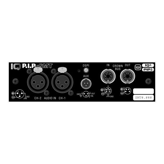
IQ P.I.P.–SMT Front View Bottom View Fig. 2.1 The IQ–P.I.P.–SMT Facilities 2 Facilities A. Mounting Screws The IQ–P.I.P.–SMT is secured to the back panel of the amplifier with two phillips-head screws and star-tooth lock washers. The lock washers are required for proper ground connec- tion. -
Page 10: Reset Switch
IQ P.I.P.–SMT the Crown Bus. A mating Switchcraft 502 series connector can be ordered from Crown (part C 7776-5). Pin 1 is negative (–), pin 2 is positive (+), and pin 3 is ground (gnd). Pins 4 and 5 are not used. - Page 11 (see Section 4.1). This switch is located on the top cir- cuit board. Each IQ component on a Crown Bus is given a unique IQ ad- dress so it can be independently controlled and monitored. Two or...
-
Page 12: Features
3 Features With an IQ–P.I.P.–SMT module a Crown amplifier can be monitored and controlled by an IQ System . And the module has SmartAmp ™ features which enable the amplifier to function automatically. For example, an IQ– P.I.P.–SMT can automatically turn off the high voltage supplies of the am- plifier when no input signal is present. -
Page 13: Input Signal Compressor/Limiter
IQ P.I.P.–SMT 3.8 Input Signal Compressor/ Limiter An input signal compressor/limiter is available for each channel. Each one is controlled by the IQ System and has five parameters: Input Compressor: Turns this function on/off. Threshold: Sets the threshold, in dB, above which the compressor acts. -
Page 14: Ioc Event Monitor
Output Limiter: Turns this function on/off. Threshold: : : : : Sets the threshold, in dB, above which the limiter acts. The level is based on the scaled output voltage monitors (see Section 3.9). The range is from 0 dB to –40 dB. Attack Time: Sets the attack time of the limiter. -
Page 15: Excessive Odep Warning
IQ P.I.P.–SMT plifier from “ ODEP limiting” the drive level of the output devices as de- scribed earlier. In the majority of cases, limiting the input signal pro- duces a very smooth sound. And since the input signal is only limited when and to the degree necessary, it is very difficult to detect. -
Page 16: Auto Standby
Auto. 3.19 Crown Bus “Drop Out” Relays “Drop out” relays are provided on the Crown Bus ports to maintain the con- tinuity of the IQ communication loop even if the IQ–P.I.P.–SMT loses power. 3.20 DSPI A Data Signal Presence Indicator (DSPI) is provided on the front panel. -
Page 17: Aux Output
IQ P.I.P.–SMT ceived. It can be forced to stay on by IQ software to assist with trouble- shooting of an IQ System . 3.21 AUX Output A 3-pin male mini XLR connector is provided to control auxiliary equip- ment. When the AUX feature is turned on, +15 VDC is provided across pin 1 (gnd) and pin 3 (+). -
Page 18: Installation
BEFORE touching IQ–P.I.P.–SMT module. For added safety, touch the outer metal collar of either Crown Bus connector (see Fig- ure 2.1). This should safely discharge any static electricity through the ground plane of the module. Avoid unnecessarily touching the compo- nents, edge connector or solder pads on the circuit boards. -
Page 19: Iq Address Switch (Sw1) Values
Crown Bus can have the same address. Suppose, for example, the IQ System has two Crown Bus loops and this IQ–P.I.P.–SMT is installed into loop 1 and given address 77. No other IQ–P.I.P.–SMT can have the same address in loop 1. -
Page 20: Input Switch (S1, S2) Location
Fig. 4.3 Input Switch (S1, S2) Location Fig. 4.4 Input Switch (S1, S2) Settings segments (S1, S2) are re- quired for each setting. Be careful to use both segments or improper operation will re- sult. Switch S1 configures the in- put to Channel 1 and switch S2 configures the input to Channel 2. -
Page 21: Prepare The Amplifier
And keep the output levels low if you are uncertain of the preamplifier settings. Re- member, Crown is not liable for damage due to overpow- ering other components. 3. Set the jumpers JP4 and JP5. If the IQ–P.I.P.–SMT is... -
Page 22: Install The Wiring
4.4 Install the Wiring 11. Connect the IQ–P.I.P.–SMT to the IQ System via the Crown Bus. See Section 4.6 for full instructions. 12. Connect the audio signal wiring to the IQ–P.I.P.–SMT . This includes the XLR input Page 22 IQ P.I.P.–SMT... -
Page 23: A Closer Look At Crown Bus Wiring
Crown Bus loop having an IQ2 -compatible IQ interface in or- der for the IQ System to control or monitor it. The Crown Bus is a serial communication loop designed to transmit IQ commands and data. As implemented in the IQ–P.I.P.–SMT , it... - Page 24 However, there are extreme situations when fiber optic wiring is recommended. For example, locat- ing a Crown Bus loop next to an AM radio transmission line may require fi- ber optic cabling. An extremely long Crown Bus loop distance may also require fiber optic cabling.
-
Page 25: Iq-P.i.p.-Smt Output To Iq Component With Din
IQ P.I.P.–SMT Figure 4.9 IQ–P.I.P.–SMT Output Connection to Another IQ Component with DIN Connectors Figure 4.10 IQ–P.I.P.–SMT Output Connectionto an IQ Component with a Screw Terminal Plug Connector Figure 4.11 An IQ Component with Screw Terminal Plug Connected to the IQ–P.I.P.–SMT Input Page 25... -
Page 26: A Closer Look At Audio Signal Wiring
Crown Bus input of the IQ–P.I.P.–SMT should be connected to an IQ com- ponent with a screw terminal plug. The IQ components in a Crown Bus loop are wired sequentially. The loop begins and ends with the IQ inter- face. The output of one IQ compo- nent “loops”... -
Page 27: Using The Aux Connector
The relay would then turn the fans on or off. This is shown in Figure 4.15. Note: A Crown part number is pro- vided in the above illustration for a suitable solid-state relay (C 7308-7). -
Page 28: The Internal Aux Circuit
2 (+). A 2.5 to 15 VDC signal at the input will be interpreted as a logic “high” and will be communicated to the Crown Bus where a host com- puter or drone can act upon it. A sig- Fig. 4.14 The Internal AUX Circuit... -
Page 29: Technical Information
A/D converter on the microprocessor, where the sig- nal is converted and sent to the host computer via the Crown Bus. The status signals that are monitored are ODEP level, IOC status and VCC status. -
Page 30: Iq System Communications
The IQ–P.I.P.–SMT communi- cates with the host computer via the Crown Bus. Connections to the Crown Bus are made via the 4 and 5-pin locking DIN connec- tors on the rear panel. IQ com- mands entering the P.I.P. are fed... -
Page 31: Iq-P.i.p.-Smt Circuit Block Diagram
IQ P.I.P.–SMT Fig. 5.1 IQ–P.I.P.–SMT Circuit Block Diagram Page 31... -
Page 32: Specifications
Indicators: A yellow DSPI (Data Sig- nal Presence Indicator) flashes when a valid IQ command is received from the IQ System via the Crown Bus. De- pending upon the firmware version in your unit, the DSPI can be forced on to facilitate rapid troubleshooting of Crown Bus wiring. - Page 33 IQ P.I.P.–SMT Frequency Response: ±0.1 dB from 20 Hz to 20 kHz. Crosstalk Ratio: >75 dB at 1 kHz. >65 dB at 20 kHz. Common Mode Rejection (CMR): >70 dB at 60 Hz with +10 dBu input. Total Harmonic Distortion (THD): <0.05% from 20 Hz to 20 kHz.
-
Page 34: Iq Address Tables
7 IQ Address Tables This section contains lookup tables for every valid IQ address. The valid addresses are 1 to 250. Remember that address “0” (zero) will put the IQ– IQ Address Switch Address Fig. 7.1 IQ Address Switch (SW1) Settings from 0 to 83 Page 34 IQ P.I.P.–SMT P.I.P.–SMT into a stand-alone mode... -
Page 35: Iq Address Switch (Sw1) Settings From 84 To 167
Remember: Remember: No two IQ components Remember: of the same type which are con- nected to the same Crown Bus loop can have the same address. IQ Address Switch Address Fig. 7.2 IQ Address Switch (SW1) Settings from 84 to 167... -
Page 36: Iq Address Switch (Sw1) Settings From 168 To 250
IQ Address Switch Address Fig. 7.3 IQ Address Switch (SW1) Settings from 168 to 250 Page 36 IQ P.I.P.–SMT IQ Address Switch Address... -
Page 37: Service
Factory Service Shipping Instruc- tions: 1. When sending a Crown product to the factory for service, be sure to fill out the service information form that follows and enclose it inside your unit’s shipping pack. Do not send the service information form sepa- rately. - Page 38 Telephone: 219-294-8200 800-342-6939 (North America, Puerto Rico, and Virgin Islands only) Facsimile: 219-294-8301 Fax Back: 219-293-9200 800-294-4094 (North America only) Internet: http://www.crownaudio.com Page 38 IQ P.I.P.–SMT If you have any questions, please call or write the Crown Technical Support Group.
- Page 39 IQ P.I.P.–SMT Crown Factory Service Information Shipping Address: Crown International, Inc., Factory Service, Plant 2 SW, 1718 W. Mishawaka Rd., Elkhart, IN U.S.A. 46517 Phone: 1-800-342-6939 or 1-219-294-8200 Fax: 1-219-294-8124 Owner’s Name: __________________________________________________________ Shipping Address: ______________________________________________________ Phone Number: ________________________ Fax Number: ____________________...
Need help?
Do you have a question about the IQ-P.I.P-SMT and is the answer not in the manual?
Questions and answers