Table of Contents
Advertisement
Quick Links
IQ-PIP-Lite Operation Manual
®
An IQ System
Programmable Input Processor with TCP/IQ
Connectivity, SmartAmp™ Features and Load Supervision for
Crown PIP2™-Compatible Amplifiers.
Obtaining Other Language Versions: To obtain information in another language about
the use of this product, please contact your local Crown Distributor. If you need assistance
locating your local distributor, please contact Crown at 574-294-8000.
This manual does not include all of the details of design, production, or variations of the
equipment. Nor does it cover every possible situation which may arise during installation,
operation or maintenance. If special assistance is needed beyond the scope of this manual,
please contact the Crown Technical Support Group.
The information provided in this manual was deemed accurate as of the publication date.
However, updates to this information may have occurred. To obtain the latest version of this
manual, please visit the Crown website at www.crownaudio.com.
Trademark Notice: Crown, Amcron, Com-Tech, Macro-Tech, IQ and IQ System are reg-
istered trademarks of Crown International. SmartAmp, IQ2, PIP and PIP2 are trademarks of
Crown International. Other trademarks are the property of their respective owners.
®
Some models may be exported under the name Amcron.
©2002 by Crown Audio Inc., P.O. Box 1000, Elkhart, Indiana 46515-1000 U.S.A.
Telephone: 574-294-8000
134719-1A
11/02
Advertisement
Table of Contents

Related Manuals for Crown IQ-PIP-LITE


Summary of Contents for Crown IQ-PIP-LITE
- Page 1 Crown PIP2™-Compatible Amplifiers. Obtaining Other Language Versions: To obtain information in another language about the use of this product, please contact your local Crown Distributor. If you need assistance locating your local distributor, please contact Crown at 574-294-8000. This manual does not include all of the details of design, production, or variations of the equipment.
-
Page 2: Fcc Compliance Notice
• Increase the separation between the equipment and receiver. • Connect the equipment into an outlet on a circuit different from that to which the receiver is connected. • Consult the dealer or an experienced radio/TV technician for help. page 2 Crown Technical Support WARNING IQ-PIP-Lite Operation Manual... -
Page 3: Declaration Of Conformity
CF23 8ND United Kingdom Equipment Type: Control System Components Family Name: IQ Model Name: IQ-PIP-Lite EMC Standards: EN 55103-1:1995 Electromagnetic Compatibility – Product Family Standard for Audio, Video, Audio- Visual and Entertainment Lighting Control Apparatus for Professional Use, Part 1: Emissions... -
Page 4: Quick Install Procedure
This procedure is provided for those who would like to install the IQ-PIP-Lite in the shortest time possible and are already familiar with Crown’s IQ System and TCP/IQ. Less experienced installers or those wishing a full explanation of the installation procedure are encouraged to go to Section 3 where the full installation procedure is described. -
Page 5: Table Of Contents
1.2 How to Use This Manual ... 9 2 Controls, Indicators and Connectors ... 10 3 Installation ... 11 3.1 Prepare the IQ-PIP-Lite ... 11 3.2 Prepare the Amplifier ... 11 3.3 Install the PIP Lite Into the Amplifier ... 12 3.4 Install the Wiring ... - Page 6 6.2.1 Typical Load Characteristics ... 31 7 Specifications ... 32 7.1 General ... 32 7.2 Audio ... 32 8 Using the IQ-PIP-Lite with the IQ PIP USP2 Adapter .. 33 9 Troubleshooting ... 37 10 Service ... 38 10.1 Worldwide Service ... 38 10.2 US and Canada Service ...
-
Page 7: Illustrations
IQ-PIP-Lite 2.1 Front Panel Controls, Connectors and Indicators ... 9 3.1 Installing the IQ-PIP-Lite into the Amplifier ... 11 4.1 Signal Flow Block Diagram ... 13 5.1 Input Wiring for the IQ-PIP-Lite ... 22 5.2 A TCP/IQ Network ... 23 5.3 Multiple Network Communication Via an IP Router ... -
Page 8: Welcome
The IQ-PIP-Lite is NOT compatible with older Crown PIP amplifiers unless a USP2 adapter is first installed in the amplifier. See Section 8 for more detail on the USP2 adapter. -
Page 9: How To Use This Manual
It does not cover every aspect of installation, setup or operation that might occur under every condition. For additional information, please con- sult Crown Tech Support, your system installer or retailer. We strongly recommend that you read all instructions, warnings and cautions contained in this manual. -
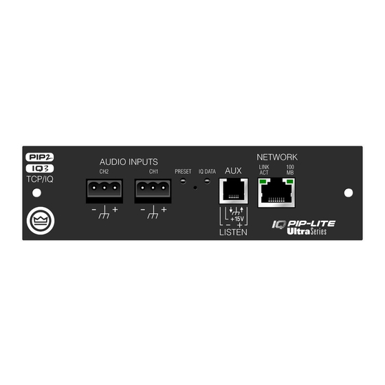
Page 10: Controls, Indicators And Connectors
During operations of the switch, the Data indicator flashes as an aid to the user. See Section 4.1.8. D. IQ Data Indicator Flashes when the IQ-PIP-Lite receives a valid TCP/IQ command that is addressed to the IQ-PIP-Lite. See Section 4.1.1. E. AUX Connector Configurable for AUX input, AUX output, or Listen Bus. -
Page 11: Installation
The IQ-PIP-Lite comes ready to install in the amplifier. This unit does not require setting the “IQ address” as the older current loop, Crown bus, units did. Each IQ-PIP-Lite (as well as all TCP/IQ components) come preprogrammed with a unique network (MAC) address. The IQ address is then set (automatically or manually) via the IQ control software. -
Page 12: Install The Pip Lite Into The Amplifier
Figure 3.1 Installing the IQ-PIP-Lite Into the Amplifier page 12 3.3 Install the IQ-PIP-Lite Into the Amplifier Carefully ground yourself to the chassis of the amplifier before installing the IQ-PIP-Lite. It is a good idea to maintain ground contact between yourself and the amplifier while inserting the mod- ule into the amplifier. -
Page 13: Install The Wiring
RX pairs switched) to set up the PIP module for desired operation. 2. Connect the audio input wiring. The IQ-PIP-Lite module is equipped with removable bar- rier block connectors for each channel’s input. See Section 5.1 for more detail on audio wiring. -
Page 14: Operation
IQ-PIP-Lite 4 Operation With an IQ-PIP-Lite module, a Crown PIP2 amplifier can be monitored and controlled from a remote location through the use of an IQ system. The PIP module features SmartAmp capabilities that enable the amplifier to function automatically. For example, the IQ-PIP-Lite can automatically turn off the high voltage supplies of the amplifier when no input signal is present. -
Page 15: Hardware
Ethernet network. Connection is made using a standard CAT 5 cable to a network switch port. In cases where an IQ-PIP-Lite is used in stand-alone mode (not connected to an network) it can be configured using a twisted cable (TX and RX pairs swapped) directly to a computer’s network adapter port. -
Page 16: Preset/Reset Switch
• Manual mode: The output is simply controlled with a command from the IQ software. • Error reporting mode: The AUX out is active when the IQ-PIP-Lite detects an error. Each error source (Thermal, Clip, Load, Amp Fault, and Line Voltage) can be individually enabled to activate the AUX output when the error conditions are met. -
Page 17: Amplifier Control And Monitoring
Data indicator (less than 2 sec- onds) and then release. The IQ-PIP-Lite will load the next preset in the defined preset range. The range of presets is defined by the Maximum Preset and Minimum Preset con- trols. -
Page 18: Thermal Headroom Level Monitor
The thermal limiter feature of the IQ-PIP-Lite can be set to engage at a pre-selected thermal level. (See Section 4.2.23.) 4.2.6 Power/Standby Control... -
Page 19: User And Channel Labels
The host amplifier’s mode status — Stereo (Dual), Bridge-Mono, or Parallel-Mono — can be sent to the IQ-PIP-Lite with this control. IQ software then becomes aware of the ampli- fier's mode and the IQ-PIP-Lite then ignores many of the Channel 2 controls. The actual mode of the amplifier cannot be controlled by this function. -
Page 20: Auto Standby
IQ-PIP-Lite LOAD: If the load monitoring feature is activated, an error report can be generated if the load impedance falls outside the pre-selected range. See Section 4.2.25 for instructions on setting up load monitoring. 4.2.18 Auto Standby The Auto Standby feature automatically turns off either amplifier channel when no audio input signal has been detected for a period of time. -
Page 21: Peak Voltage Limiter
IQ-PIP-Lite greater of the two input signals will be used as stimulus for both compressors. Each com- pressor will still compress based on its individual threshold, attack, release and ratio set- tings. 4.2.20 Peak Voltage Limiter This limits the peak voltage output of the amplifier. Four parameters control this limiter for each channel: Enable: Enables or disables this function. -
Page 22: Limiter Tie
4.2.25 Load Supervision The load supervision feature allows real-time monitoring of the load connected to each amplifier channel. When enabled, the IQ-PIP-Lite continuously monitors the amplifier output voltage and current, and calculates the long-term average load impedance. The measured load impedance is compared against the user-defined high and low limits. If either limit is exceeded, the status indicator and, if enabled, the IQ System Error Reporting functions alert the user of the problem. -
Page 23: Audio Signal Wiring And Network Basics
• Turn the entire sound system off before changing any connections. Turn the level con- trols down before powering the system back up. Crown is not liable for damage incurred when any transducer or component is overdriven. -
Page 24: Tcp/Iq Network Basics
IQ-PIP-Lite 5.2 TCP/IQ Network Basics TCP/IQ is a network based protocol that has the ability to control and monitor IQ compo- nents over a common TCP/IP network. For IQ components that have CobraNet capability, TCP/IQ has the ability to control and monitor these IQ components over the same Ethernet network used for CobraNet audio, resulting in a single CAT-5 connection for control, moni- toring, and digital audio. - Page 25 IQ-PIP-Lite Some of the features of TCP/IQ include: • Real-time control and monitoring of IQ components. • Use of standard “off-the-shelf” Ethernet technology. • For CobraNet enabled components, a single connection for both control and CobraNet audio. • Ability to quickly discover all IQ components connected to the network.
- Page 26 LAN. The Subnet Mask associated with each IQ Compo- nent tells what IP addresses can be assigned to a particular LAN. The Subnet Mask is also page 26 Computer Computer 100Mb Switch 192.168.1.241 IQ-PIP-Lite IP Router 100Mb Switch Wireless Access Point Wireless Devices...
- Page 27 IQ-PIP-Lite four numbers (0-255) separated by periods. For example, a subnet mask of 255.255.255.0 and an IP address of 192.168.1.123 says that all IP address in that LAN are in the IP address range of 192.168.1.1 to 192.168.1.255. If a TCP/IQ controller is on a different network than the TCP/IQ components, communica- tions must occur through an IP router.
-
Page 28: Advanced Features And Options
6 Advanced Features and Options 6.1 Using the AUX Connector The AUX connector of the IQ-PIP-Lite offers a means to tap some of the flexibility of the IQ System. It can be used to enable peripherals, send a signal to another system component, and send a line-level audio signal of the amplifier's output. - Page 29 IQ-PIP-Lite The AUX output has two enhanced modes: Error Reporting and Flash Preset. In Error Reporting mode, the AUX port can be set up to change state when any selected error (clip, thermal, amp fault, load impedance, and AC line level) is detected. With this feature, the AUX output of each amplifier can be wired to a separate light on a panel at the control loca- tion to indicate whether the amplifier is or is not in error.
-
Page 30: Aux Input
6.2 Load Supervision Applications The IQ-PIP-Lite Load Supervision feature can be used to monitor the amplifier load in real time with almost any program material. Average load impedance is calculated as a function of amplifier output voltage and current. -
Page 31: Typical Load Characteristics
The low frequency variations are usually wide bandwidth and may vary from 6 to 30 ohms on an 8-ohm driver. These anomalies are easily averaged out by the IQ-PIP-Lite supervision algorithm in most systems. However, there may be some extreme situations for very narrow bandwidth (i.e. -
Page 32: Specifications
Capable of 10,000 write cycles. Power Requirements: 160 mA at +24 VDC and 50 mA at –24 VDC. When installed into a Crown PIP2 compatible amplifier, the unit receives ± 24 VDC from the amplifier. No exter- nal power is required. -
Page 33: Using The Iq-Pip-Lite With The Iq Pip Usp2 Adapter
Group for installation instructions. Important: The IQ-PIP-USP2 Adapter is designed for use with the IQ-PIP-USP2 module and IQ-PIP-Lite ONLY, and will NOT work with the IQ-PIP-USP2/CN or any other PIP module. Please note the following differences when using the IQ-PIP-Lite with the IQ-PIP-USP2... -
Page 34: Signal Path" Tab Showing Peak Voltage And Average
IQ-PIP-Lite Figure 8.1 “General” Tab Showing Identification of IQ-PIP-USP2 Adapter Peak Voltage and Average Power Voltage Limiter Peak Voltage and Average Power Limiters are not available. Figure 8.2 “Signal Path” Tab Showing Peak Voltage and Average Power Limiters Disabled page 34... -
Page 35: Disabled
IQ-PIP-Lite Figure 8.3 “Peak Voltage Limiter” Block Disabled on “Signal Path” Tab Figure 8.4 “Average Power Limiter” Block Disabled on “Signal Path” Tab page 35 Operation Manual... -
Page 36: Error Reporting" Tab Showing Fault And Load Error
Figure 8.5 “Error Reporting” Tab Showing Fault Figure 8.6 “Load Supervision” Tab Showing page 36 Fault and Load Error Reporting Fault and Load Error Reporting are not available. and Load Error Reporting Disabled Load Supervision Load Supervision is not available. Load Supervision Disabled IQ-PIP-Lite Operation Manual... -
Page 37: Troubleshooting
• Data cable is disconnected or broken. To assist with troubleshooting, an option that forces the data indicator to remain lit is available through the IQ software. Some Crown amplifi- ers also have a data indicator on their front panels. In these cases this indicator will light simultaneously with the PIP's data indicator. -
Page 38: Service
10.2.1 Factory Service To obtain factory service, fill out the service information page found in the back of this manual and send it along with your proof of purchase and the defective unit to the Crown factory. For warranty service, we will pay for ground shipping both ways in the United States. Con- tact Crown Factory Service to obtain prepaid shipping labels prior to sending the unit. - Page 39 If you don't have the original carton, you may obtain a product service foam-in-place ship- ping pack from Crown Factory Service at the number listed below. For non-warranty ser- vice, you may also provide your own shipping pack, however we still recommend using a Crown supplied shipping container.
-
Page 40: Warranty
Crown International, 1718 West Mishawaka Road, Elkhart, Indiana 46517-4095 U.S.A. warrants to you, the ORIGINAL PURCHASER and ANY SUBSEQUENT OWNER of each NEW Crown product, for a period of three (3) years from the date of purchase by the original purchaser (the “warranty period”) that the new Crown product is free of defects in materials and workmanship. -
Page 41: Summary Of Warranty
ITEMS EXCLUDED FROM THIS CROWN WARRANTY This Crown Warranty is in effect only for failure of a new Crown product which occurred within the Warranty Period. It does not cover any product which has been damaged because of any intentional misuse, accident, negligence, or loss which is covered under any of your insurance contracts. - Page 42 IQ-PIP-Lite NOTES page 42 Operation Manual...
-
Page 43: Factory Service Information Form
Crown Factory Service Information Shipping Address: Crown Factory Service, 1718 W. Mishawaka Rd., Elkhart, IN U.S.A. 46517 Phone: 1-800-342-6939 or 1-574-294-8200 Fax: 1-574-294-8124 Owner’s Name: __________________________________________________________ Shipping Address: _______________________________________________________ Phone Number: __________ Fax Number: ___________ Email: __________________ Model:________________________________ Serial Number: __________________...
Need help?
Do you have a question about the IQ-PIP-LITE and is the answer not in the manual?
Questions and answers