Table of Contents
Advertisement
Quick Links
An IQ System
®
Programmable Input Processor with DSP
for Crown
®
P.I.P.
®
-compatible Power Amplifiers
©1999 by Crown International, Inc., P.O. Box 1000, Elkhart, Indiana 46515-1000 U.S.A. Telephone: 219-
294-8000. The IQ–P.I.P.–DSP is produced by Crown International, Inc. Trademark Notice: MPX-6
™
, SMX-
6
™
, SmartAmp
™
and Macro Reference
™
are trademarks and Amcron
®
, Crown
®
, IQ System
®
, IOC
®
, ODEP
®
,
Macro-Tech
®
, Com-Tech
®
and P.I.P.
®
are registered trademarks of Crown International, Inc. Other
Printed on
trademarks are the property of their respective owners.
recycled paper.
103291-2
9/99
Advertisement
Table of Contents

Subscribe to Our Youtube Channel
Related Manuals for Crown IQ P.I.P.-DSP


Summary of Contents for Crown IQ P.I.P.-DSP
- Page 1 An IQ System ® Programmable Input Processor with DSP for Crown ® P.I.P. ® -compatible Power Amplifiers ©1999 by Crown International, Inc., P.O. Box 1000, Elkhart, Indiana 46515-1000 U.S.A. Telephone: 219- 294-8000. The IQ–P.I.P.–DSP is produced by Crown International, Inc. Trademark Notice: MPX-6 ™...
-
Page 2: North America
IQ–P.I.P.–DSP Programmable Input Processor with DSP for IQ Systems THREE YEAR NORTH AMERICA The Crown Audio Division of Crown International, Inc., 1718 West Mishawaka Road, Elkhart, Indiana 46517-4095 U.S.A. warrants to you, the ORIGINAL PURCHASER and ANY SUBSEQUENT OWNER of each NEW Crown prod- uct, for a period of three (3) years from the date of purchase by the original purchaser (the “warranty period”) that the new Crown product is free of defects... -
Page 3: Important Safety Instructions
IQ–P.I.P.–DSP Programmable Input Processor with DSP for IQ Systems Important Safety Instructions 1) Read these instructions. 2) Keep these instructions. 3) Heed all warnings. 4) Follow all instructions. 5) Do not use this apparatus near water. 6) Clean only with a damp cloth. 7) Do not block any of the ventilation openings. -
Page 4: Fcc Compliance Notice
If you need special assistance beyond the scope of this manual, please contact our Technical Support Group. Crown Audio Division Technical Support Group Plant 2 SW, 1718 W. Mishawaka Rd., Elkhart, Indiana 46517 U.S.A. Phone: 800-342-6939 (North America, Puerto Rico and Virgin Islands) or 219-294-8200 Fax: 219-294-8301 Fax Back (North America only): 800-294-4094 or 219-293-9200 Fax Back (International): 219-294-8100 Internet: http://www.crownaudio.com... -
Page 5: Quick Install Procedure
IQ–P.I.P.–DSP Programmable Input Processor with DSP for IQ Systems This procedure is provided for those who are already familiar with Crown’s IQ System and who would like to install the IQ–P.I.P.–DSP in the shortest time possible. Less experienced installers or those wishing a full explanation of the installation procedure are encouraged to go to Section 4 where the full installation procedure is described. -
Page 6: Table Of Contents
Quick Install Procedure ... 5 1 Welcome ... 7 Unpacking ... 7 2 Facilities ... 8 3 Installation ... 10 Prepare the IQ–P.I.P.–DSP ... 10 Prepare the Amplifier ... 11 Install the IQ–P.I.P.–DSP into the Amplifier ... 11 Install the Wiring ... 11 Adjust the Levels &... -
Page 7: Welcome
IQ–P.I.P.–DSP Programmable Input Processor with DSP for IQ Systems 1 Welcome The IQ–P.I.P.–DSP is a powerful IQ component that con- nects an IQ-compatible amplifier to the Crown Bus of an IQ System so the amplifier can be controlled and monitored. Its DSP (digital signal processing) capabili- ties enable it to offer a variety of programmable func- tions, such as filters and crossovers, signal delay, input compressor and output limiter and a variety of other... -
Page 8: Facilities
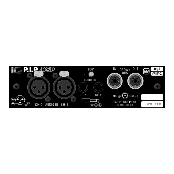
P.I.P. - DSP PUSH Front View C H - 2 Bottom View 2 Facilities A. Mounting Screws The IQ–P.I.P.–DSP is secured to the back panel of the amplifier with two phillips-head screws and star-tooth lock washers. The lock washers are required for proper ground connection. - Page 9 IQ–P.I.P.–DSP Programmable Input Processor with DSP for IQ Systems D. Reset Switch A multifunction reset switch is provided to restore the IQ–P.I.P.–DSP to a prior state. It can be depressed with a straightened paper clip through the small hole in the P.I.P.
-
Page 10: Installation
3 Installation Before beginning, please carefully note: CAUTION: STATIC ELECTRICITY MAY DAMAGE THE IQ–P.I.P.–DSP MODULE. Use caution when handling the unit. Carefully ground yourself BEFORE touching the IQ–P.I.P.–DSP module. For added safety, touch the outer metal collar of either Crown Bus connector (see Figure 2.1). -
Page 11: Prepare The Amplifier
IQ–P.I.P.–DSP Programmable Input Processor with DSP for IQ Systems settings for all 250 addresses. 2. Set the jumpers JP4 and JP5. If the IQ–P.I.P.– DSP is being installed into a PIP2 -compatible or Macro-Tech 5000VZ amplifier, move both jumper JP4 and JP5 on the IQ circuit board to the “OUT”... -
Page 12: Adjust The Levels & Scale Factors
Section 3.8 for more information. 3.5 Adjust the Levels & Scale Factors 13. Turn the level controls of the amplifier to their full or maximum setting. This is required by the IQ–P.I.P.–DSP . If needed, use the software-con- trolled input attenuators on the IQ–P.I.P.–DSP to re- duce the audio levels. -
Page 13: Iq-P.i.p.-Dsp Output Toiq Component With Din
IQ–P.I.P.–DSP Programmable Input Processor with DSP for IQ Systems than 1,000 feet (305 m)—or when required by high-capacitance wire. Although we recommend adding a repeater for loops longer than 1,000 feet, it is often possible to go 2,000 feet (610 m) or more. -
Page 14: A Closer Look At Audio Signal Wiring
3.7 A Closer Look at Audio Signal Wiring Balanced 3-pin female XLR connectors are provided for audio input connection. The audio cables should be wired in one of the following manners: Fig. 3.11 Audio Input Wiring We strongly recommend that balanced wiring be used if possible. -
Page 15: Operation
IQ–P.I.P.–DSP Programmable Input Processor with DSP for IQ Systems 4 Operation With an IQ–P.I.P.–DSP module, your Crown amplifier can be monitored and controlled from a remote location through the use of an IQ System . This P.I.P. module features SmartAmp ™... -
Page 16: Polarity Inverter
4.8 Polarity Inverter The polarity of the input signal of each channel can be independently inverted by the IQ System . 4.9 Input Signal Attenuator An attenuator is available at the input of each channel to control the input signal level. These attenuators are controlled and monitored by the IQ System . -
Page 17: Auto Standby
IQ–P.I.P.–DSP Programmable Input Processor with DSP for IQ Systems output limiters are controlled by the IQ System and has five parameters: Output Limiter: Turns this function on/off. Threshold: Sets the threshold, in dB, above which the limiter acts. The level is based on the scaled output voltage monitors (see Section 4.4). -
Page 18: Excessive Odep Warning
level would indicate a sudden decrease in the load impedance—such as a shorted speaker cable or shorted loudspeaker. There are two parameters which control this feature: ODEP Short Detect: Turns this function on/off. ODEP Short Level: Sets the ODEP level above which a short is presumed to have occurred in the load resulting in a warning message being displayed. - Page 19 IQ–P.I.P.–DSP Programmable Input Processor with DSP for IQ Systems filter is commonly used to feed the high frequency portion of an audio signal to horns or tweeters. It can be combined with a low-pass crossover filter to create a band-pass crossover filter for driving mid-range drivers.
-
Page 20: Amplifier Information
4.21 Memory Backup A memory backup feature is provided which can be disabled, if desired. The factory default setting is “enabled.” When enabled, it stores all run-time parameters that can be controlled by the IQ software into nonvolatile memory (EEPROM) at approximately one second intervals. -
Page 21: Technical Information
IQ–P.I.P.–DSP Programmable Input Processor with DSP for IQ Systems 5 Technical Information The purpose of the IQ–P.I.P.–DSP is to provide extensive signal processing capabilities and to enable an IQ System to control and monitor a P.I.P. -compatible amplifier. See Sections 2 and 3 for a list of the facilities and features. -
Page 22: Control/Monitor Functions
parameters are used here such as threshold, attack time, etc. Next, the output limiter is processed through control- lable polarity inverters. The last processing section is an output muter after which the signal is sent to the main am- plifier for voltage and current amplification. All parameters are continuously controllable via the IQ System or can be set and will continue to operate. -
Page 23: Specifications
IQ–P.I.P.–DSP Programmable Input Processor with DSP for IQ Systems 6 Specifications General Internal Controls: An 8-segment DIP switch sets the IQ address (decimal range: 1–250). Note: If address “0” is selected, the IQ–P.I.P.–DSP will operate in stand- alone mode. A Reset switch, accessible with a straight- ened paper clip through the P.I.P. -
Page 24: Iq Address Tables
7 IQ Address Tables This section contains lookup tables for every valid IQ ad- dress. The valid addresses are 1 to 250. Remember that address “0” (zero) will put the IQ–P.I.P.–DSP into a stand- alone mode where it is invisible to the IQ System and acts like a “dumb”... -
Page 25: Iq Address Switch (Sw1) Settings From 126 To 250
IQ–P.I.P.–DSP Programmable Input Processor with DSP for IQ Systems IQ Address Switch Address Fig. 7.2 IQ Address Switch (SW1) Settings from 126 to 250 Reference Manual IQ Address Switch Address IQ Address Switch Address Page 25... -
Page 26: Service
Reference or Owner’s Manual , cables and other hardware. If you have any questions, please call or write the Crown Technical Support Group. Crown Audio Division Technical Support / Factory Service Plant 2 SW, 1718 W. Mishawaka Rd., Elkhart, Indiana 46517 U.S.A. - Page 27 IQ–P.I.P.–DSP Programmable Input Processor with DSP for IQ Systems Crown Factory Service Information Shipping Address: Crown International, Inc., Factory Service, Plant 2 SW, 1718 W. Mishawaka Rd., Elkhart, IN 46517 Phone: 1-800-342-6939 or 1-219-294-8200 Fax: 1-219-294-8124 Owner’s Name: _________________________________________________________________________ Shipping Address: ______________________________________________________________________ Phone Number: _____________________________ Model: ________________________ Serial Number: ______________ Purchase Date: ___________ (Be sure to describe the conditions that existed when the problem occurred and what attempts were made to correct it.)
Need help?
Do you have a question about the IQ P.I.P.-DSP and is the answer not in the manual?
Questions and answers