Advertisement
Quick Links
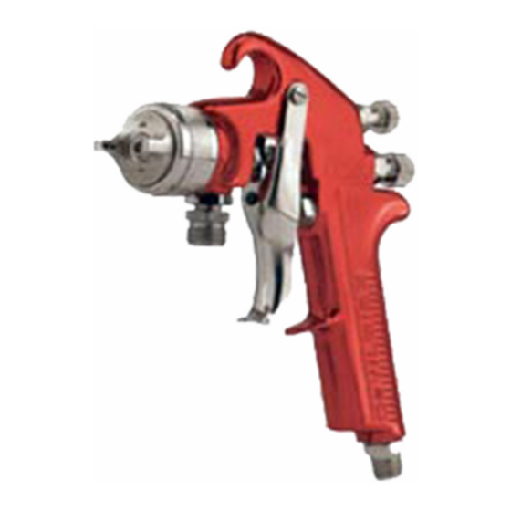
EXL-520S HIGH VOLUME LOW PRESSURE SUCTION FEED SPRAY GUNS
IMPORTANT: Before using this equipment,
read all safety precautions and instructions.
Keep for future use.
DESCRIPTION
These compliant high volume low pressure
suction feed EXL guns are designed to
apply a wide variety of finishing materials.
The guns were manufactured to provide
maximum transfer efficiency by limiting air
cap pressure to 10 psi (complies with rules
issued by SCAQMD and other air quality
authorities).
These guns will produce approximately 10
psi cap pressure at 30 psi gun inlet pres-
sure. Air cap test kits are available (see
ACCESSORIES) which can be utilized to set
the exact air cap pressure. Air consumption
for the EXL-520S (#2000 cap) is 15.5 SCFM
at 10 psi air cap pressure.
This gun should not be used with
chlorinated solvent materials.
Halogenated hydrocarbon solvents
(for example: methylene chloride
and 1, 1, 1, - Trichloroethane)
are not chemically compatible
with the aluminum that might be
used in many system components.
The chemical reaction caused
by these solvents reacting with
aluminum can become violent
and lead to equipment explosion.
See page 2 for potential hazards.
Important: These guns may be used with
most common coating and finishing mate-
rials. They are designed for use with mildly
corrosive and non-abrasive materials. If
used with other high corrosive or abrasive
materials, it must be expected that fre-
quent and thorough cleaning will be re-
quired and the necessity for replacement of
parts will be increased.
INSTALLATION
For maximum transfer efficiency, do not
use more pressure than is necessary to
atomize the material being applied.
1 .
Connect the gun to a clean, moisture
and oil free air supply using a hose size
of at least 5/16" I.D. hose. Do not use
1/4" I.D. hose (25' x 1/4" hose at 18 CFM
has a pressure loss of 25 psi. 25' x 5/16"
hose at 18 CFM has a pressure loss of
8 psi).
Note
Depending on hose length, larger
I.D. hose may be required. Install an
HAV-501 air gauge at the gun handle
and air cap test kit over tip. When
gun is triggered on, adjust regulated
pressure to desired setting to
provide a maximum of 10 psi at the
air cap. Do not use more pressure
than is necessary to atomize the
material being applied. Excess pres-
sure will create additional overspray
and reduce transfer efficiency.
Note
If quick connects are required, use
only high flow quick connects
approved for HVLP use such as
DeVilbiss HC-4419 and HC-4699.
Other types will not flow enough air
for proper gun operation.
Note
If an air adjusting valve is used at the
gun inlet, use DeVilbiss Model HAV-
500 or HAV-501. Some competitive
adjusting valves have significant
pressure drop that can adversely
affect spray performance. Models
HAV-500 and HAV-501 have minimal
pressure drop, which is important for
HVLP spraying.
2 .
Attach the suction feed cup to the
material inlet.
Note
Protective coating and rust inhibi-
tors have been used to keep the
gun in good condition prior to ship-
ment. Before using the gun, flush it
with solvents so that these materi-
als will be removed from fluid pas-
sages.
OPERATION
Mix, prepare and strain the material to be
sprayed according to the paint maufacturer's
instructions.
Strain material through a 60 or 90 mesh
screen.
1 .
Fill the suction feed cup with the
material. Do not overfill. Make sure
that the cup lid vent hole is clear.
2.
Open the spreader adjustment valve
(10) (Fan) by turning the valve stem
counterclockwise.
3.
Open fluid adjusting screw (17) by turn-
ing counterclockwise.
SERVICE BULLETIN
SB-2-496-A
Replaces SB-2-496
Repair Kit KK-5058-2
4.
Turn on air supply and set gun inlet
pressure to lowest recommended pres-
sure for material being sprayed. Spray a
test area. Air pressure and paint flow
should be adjusted to provide a uniform
dispersion of atomized paint throughout
the pattern. Keep air pressure as low
as possible to minimize bounce-back
and overspray. Excessive fluid flow
will result in heavy center spray pat-
terns. Inadequate flows may cause
the patterrn to split. See TROUBLE-
SHOOTING, Page 5, if any problems
occur. If finer atomization is required,
increase gun inlet pressure. If a re-
duced fluid flow rate is required, turn
fluid adjusting screw (17) clockwise
until desired fluid flow is obtained.
See Spray Gun Guide, SB-2-001 latest revi-
sion, for details concerning setup of spray
guns.
PREVENTIVE MAINTENANCE
To clean air cap and fluid tip, brush exterior
with a stiff bristle brush. If necessary to
clean cap holes, use a broom straw or
toothpick if possible. If a wire or hard instru-
ment is used, extreme care must be used to
prevent scratching or burring of the holes
which will cauase a distorted spray pattern.
To clean fluid passages, remove excess
material from cup, then flush with a suitable
solvent. Wipe gun exterior with a solvent
dampened cloth. Never completely immerse
in solvent as this is detrimental to the lubri-
cants and packings.
Note
When replacing the fluid tip or
fluid needle, replace both at the
same time. Using worn parts can
cause a defective spray pattern.
See Chart 2. Also, replace the
needle packing at this time. Lightly
lubricate the threads of the fluid
tip before reassembling. Torque
to 12-15 ft. lbs. Do not overtighten
the fluid tip.
To prevent damage to fluid tip (5)
or fluid needle (11), be sure to
either 1) pull the trigger and hold
while tightening or loosening the
fluid tip, or 2) remove fluid needle
adjusting screw (17) to relieve
spring pressure against needle
collar.
Advertisement

Related Manuals for DeVilbiss EXL-520S


Summary of Contents for DeVilbiss EXL-520S
- Page 1 SERVICE BULLETIN SB-2-496-A Replaces SB-2-496 Repair Kit KK-5058-2 EXL-520S HIGH VOLUME LOW PRESSURE SUCTION FEED SPRAY GUNS IMPORTANT: Before using this equipment, Note Turn on air supply and set gun inlet read all safety precautions and instructions. pressure to lowest recommended pres- Keep for future use.
-
Page 2: Safety Precautions
Page 2 SB-2-496-A SAFETY PRECAUTIONS This manual contains information that is important for you to know and understand. This information relates to USER SAFETY and PREVENTING EQUIPMENT PROBLEMS. To help you recognize this information, we use the following symbols. Please pay particular attention to these sections. - Page 3 SB-2-496-A Page 3 SPRAY GUN LUBRICATION PARTS REPLACEMENT 11. After each adjustment, pull needle Figure 1 Air Cap open and observe needle closure. Daily, apply a drop of SSL-10* spray gun 1 2 . If needle snaps shut, continue lube at trigger bearing stud (28) and the adjusting nut until there is evidence stem of air valve (20) where it enters air of needle bind or slow closing.
-
Page 4: Parts List
Page 4 SB-2-496-A 36 37 38 Air Inlet Nipple 1/4" NPS(M) Fluid Tip (torque to 15 ft. lbs.) (Torque to 12-15 ft. lbs.) *Use medium strength Fluid Inlet Nipple thread sealant (i.e. 3/8" NPS(M) Devcon #2242 Blue, or (torque to 20-25 ft. equal) on threads. - Page 5 SB-2-496-A Page 5 TROUBLESHOOTING CONDITION CAUSE CORRECTION Horn holes plugged. Clean. Ream with non-metallic point. Heavy top or Clean. Obstruction on top or bottom of fluid tip. bottom pattern Cap and/or tip seat dirty. Clean. Left or right side horn holes plugged. Clean.
-
Page 6: Warranty
MSDS Sheet available upon request. atmospheres not immediately dangerous to life. WARRANTY This product is covered by DeVilbiss' 1 Year Limited Warranty. DeVilbiss Worldwide Sales and Service Listing: www.devilbiss.com ITW Industrial Finishing DeVilbiss has authorized distributors throughout the world. For technical assistance or the distributor nearest you, see listing below.
Need help?
Do you have a question about the EXL-520S and is the answer not in the manual?
Questions and answers