Table of Contents
Advertisement
BCD396XT
The Complete Reference
Friday, November 07, 2008
This document provides a complete reference to all menus, functions, and
features of the BCD396XT Digital Trunk Tracker Scanner from Uniden. It is
based on the Operation Specification that is used both as a guide to the
implemented.
Some proprietary information has been removed, formatting has been
modified, and extensive editing has been performed to make the text
more readable. However, you will almost certainly find a handful of odd
turns of phrases.
Mostly, though, we hope that this reference work can help you better
available to scanner users online, you now have more information than
ever on every facet of your scanner.
© 2009 Uniden Corporation
Fort Worth, TX
All Rights Reserved.
1
intended to be a
Advertisement
Table of Contents

Related Manuals for Uniden BCD396XT


Summary of Contents for Uniden BCD396XT
- Page 1 The Complete Reference This document provides a complete reference to all menus, functions, and features of the BCD396XT Digital Trunk Tracker Scanner from Uniden. It is based on the Operation Specification that is used both as a guide to the implemented.
- Page 2 Contents Feature Summary ......................8 Band Coverage ......................8 Channels ........................9 Memory Architecture ..................... 9 Channel Memory Scan ....................9 Priority Scan........................9 Priority Plus Scan......................9 Search with Scan ......................9 Scan Speed........................9 Scanning Lockout ......................10 Temporary Lockout .......................
-
Page 3: Table Of Contents
IF Exchange ........................12 Dropout Delay ....................... 13 Weather and SAME Alert....................13 ® Close Call Frequency Capture ..................13 Close Call Temporary Store ..................13 Tone-Out Sequential Decode ..................13 Location-Based Scanning* ................... 13 Location Alert System*....................13 Navigation Modes* ......................13 GPS Compatibility* ....................... - Page 4 Alert for Point Of Interest ..................24 Alert for Dangerous Xing..................24 Alert for Dangerous Road ..................24 Battery Low Tone ......................24 Operation ........................... 25 Power On ........................25 Volume and Squelch Control ..................26 Volume Adjust Mode ....................26 Squelch Adjust Mode ....................
- Page 5 Quick Save for CTCSS/DCS/P25 NAC Data ............128 Key Operation During Scan ..................129 SCAN HOLD MODE ..................... 131 Display while in Scan Hold Mode ................131 General Operation....................131 Hold on Conventional System ................. 135 Hold on Trunked System ..................135 Hold on TalkGroup ID from ID Search / ID Scan .............
- Page 6 Close Call Auto Store....................161 CC Hit with Scan ...................... 162 Direct Entry / Quick Save / Go to Quick Search Hold Mode ........162 Key Operation During Close Call Only Mode ............163 Key Operation During Close Call Hold Mode ............164 WEATHER SCAN MODE .....................
- Page 7 Error State ........................ 197 Key Operation During Clone Mode................197 KEYLOCK ........................198 KEY SAFE MODE......................199 Changed Key Operation in Key Safe Mode ............. 199 Key Safe Operation....................200 Key Safe Message ....................200 MEMORY INITIALIZATION ..................201 BATTERY CHARGE ..................... 202 Battery Type Select....................
- Page 8 25 cm Amateur Band Notes on Band Coverage: You can edit the Modulation and Step for each band. The above table shows the factory default values. Although TV bands are listed, the BCD396XT cannot decode Digital TV audio. Friday, November 07, 2008...
- Page 9 Channels Dynamic You can create up to 25,000 total conventional channels, trunked channels, and trunked system frequencies. Channels in a conventional system contain a frequency. Channels in a trunked system contain a talk group ID (TGID). Memory Architecture Absolute Limits: Systems Sites Total 1,000...
- Page 10 Scanning Lockout You can lock out any System, Site, Channel Group, Channel, or search frequency. Locked out channels are skipped (or ignored) during scanning. If a system, site, or channel group is locked, all channels belonging to it will be skipped during scanning. Temporary Lockout Sites, Systems, Channels, or Frequencies temporarily locked out are automatically unlocked when power is cycled.
- Page 11 Multi-Site System All trunked systems can have more than one site. All sites in the system share the same Channel Groups and Channels. Control Channel Only Trunk Tracking can be achieved by entering only the control channels for Motorola and P25 systems. P25 One-Frequency Trunking The scanner can follow individual talk groups on P25 single-frequency systems that use both NAC and s for squelch control and user identification.
-
Page 12: If Exchange
Search Lockout You can lock out up to 500 frequencies. The limit of temporary L/O frequencies: 250 The limit of permanent L/O frequencies: 250 Locked out frequencies will be skipped in Search Mode or Close Call Mode. You can review all locked out frequencies in Menu Mode. Search Key Search keys are short cuts to start searching for a single search range. -
Page 13: Dropout Delay
Wired Cloning You can clone all programmed data, including Memory Architecture, Menu settings and other parameters from one BCD396XT to another BCD396XT connected with RS232C cable. Band Scope Band Scope Mode searches a frequency range and displays a graphic of the signal level in real time. -
Page 14: Pc Control
PC Control You can download information into the scanner and control the scanner via your personal computer. LCD and Keypad Backlight You can select your desired LCD backlight color from White, Red, Magenta, Blue, Green, Cyan, or Yellow. The Keypad backlight is single white. The backlight can be adjusted to 3 different brightness levels Alert Tone Level This feature lets you adjust the volume level of the following tones: Key Beep, Emergency Alert, Channel... -
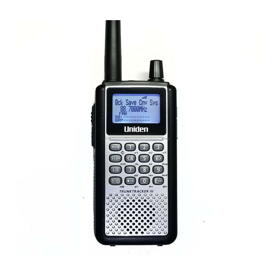
Page 15: Design
Design The below is a design reference. There might be some differences between this image and the actual final design. Friday, November 07, 2008... -
Page 16: Controls And Keys
Controls and Keys Long press means pressing a key more than 2 second. Normal Mode: Normal Mode means that the scanner is not in Function Mode. In this mode, the icon is not displayed. Function Mode: Pressing [FUNC] puts the scanner into Function Mode for 3 seconds. While it is in Function Mode, the scanner displays the icon. - Page 17 Function + Scan / srch Key Press to resume searching. (Search Hold Mode and while monitoring in Search Mode) Press to toggle between ID SCAN and ID SEARCH while scanning a trunked system. Press to display the Quick Search Prompt. (Except in Search Mode, Search Hold Mode, GPS Mode and Band Scope Mode) Press to return to the scanner screen.
- Page 18 Function + L/O Key Press once to temporarily lock out the current system, current site or current search range in Scan Mode and Scan Hold Mode. This lock out is cleared when power is turned off then back on. Press twice in a second to permanently lock out the current system or current search range in Scan Mode and Scan Hold Mode.
- Page 19 Function + 6 / RIGHT / disp Key Press to change the Display Mode. (Scan Hold Mode and Custom Search Mode) (Display mode 1 -> Display mode 2 -> Display mode 3 -> Display mode 1 - Press to change the GPS Display. (GPS Mode) Function + 7 / att (Attenuator) Key Press to toggle the attenuation state.
- Page 20 Menu Key Press to enter the Menu Mode. Press to go back up one menu level when in the Menu Mode. Press after entering the value to indicate going to a number tagged system or channel. Function + Menu Key Press to go to the editing menu for the current system, search range or location data.
-
Page 21: Displays
Displays LCD Design The reference design shown below is for illustration purposes only and is not intended to be a photorealistic representation of the display. HOLD L/O PRI ABCDEFGHI JKLMNOP abcdefghi jklmnop S0: 1 2 3 4 5 6 7 8 9 0 GRP 1 2 3 4 5 6 7 8 9 0 Icons Sx: :... -
Page 22: Dot Matrix
LNK: This icon appears when data is received on a VOICE CHANNEL. This shows in the same place as "P25". DAT: This icon appears when data on CONTROL CHANNEL is received. This shows in the same place as "P25" icon. ENC: This icon appears when encrypted APCO P25 digitized voice is received. -
Page 23: Tones
Tones The scanner can produce 3 fundamental tones, high (1200 Hz), middle (920 Hz), and low (640 Hz). Furthermore, there are Alert Tones and Weather Alert Sirens which include other sounds. Additionally, special alert tones (Location Alert, CC alert, Emergency alert and WX alert, etc) can be set to custom volume levels. -
Page 24: Tones In Menu Mode
Tones in Menu Mode Selecting a menu item As you step to the next menu item by turning [Scroll Control] knob, the scanner will sound a single high beep for 100 ms. However, if the menu item is the last item and you turn [Scroll Control] knob in the clockwise direction, the scanner will sound a double high beep (75 ms beep - 25 ms silent - 75 ms beep). -
Page 25: Operation
If ID has not been registered yet, LAST MODE will be Scan Mode. Review Location Mode is set to normal Scanner Mode (not GPS Mode). Uni den Bearcat Copyri ght 2009 BCD396XT Uni den Ameri ca Di gi tal Trunki ng Corp. All Ri ghts Dynami c Scanni ng Reserved. -
Page 26: Volume And Squelch Control
Volume and Squelch Control Volume and Squelch can be adjusted by rotating the [Scroll Control] in the following modes: Scan Mode, Scan Hold Mode, Search Mode, Search Hold Mode, Tone-Out Mode, Weather Scan Mode, Close Call Only Mode, Band Scope Mode, Band Scope Hold Mode. Volume Adjust Mode To adjust the volume level, press [Scroll Control]. -
Page 27: P25 Condition Mode
P25 Condition Mode Press [Function] + [Scroll Control] key to go to P25 Condition mode in Volume / Squelch Adjust mode. You can see the current status of APCO decoding and the threshold values in this mode. 3. 87 Battery Voltage System 1 25. -
Page 28: Menu Mode
Menu Mode General Operations Key Operation To enter the Menu Mode: Press [Menu] To select a Menu item: Turn [Scroll Control] To select a Menu item or input data: Press [E / yes / gps] or tap the [Scroll Control] To Return to the previous: Press [Menu] To exit from Menu Mode: Press [Scan / srch] to go to Scan Mode... - Page 29 Edit Name The editing cursor is displayed. Turn [Scroll Control] to choose the character and the cursor stays at the highlighted position. The display is the following. Edi t Name System 1 cursor Press [4 / LEFT / ifx] to move the cursor to the left and [6 / RIGHT / disp] to move it to the right. Press [.
- Page 30 Edit Frequency and Set Tone The editing cursor is displayed. Press a number key to enter each digit and press the decimal key to input a decimal point. The cursor moves to the left or the right by turning [Scroll Control] knob. If you press the decimal key when a decimal point is already entered, the frequency data is cleared and the editing cursor moves to the first position.
-
Page 31: Error Messages
Hexadecimal TGID edit Turn the [Scroll Control] to select Hexadecimal characters from 0 to F , Press [4 / LEFT / ifx] to move the cursor left or press [6 / RIGHT / disp] to move cursor right. Press [E / yes / gps] to set the Hex ID. Note: You can change the TGID format in Set ID Format (DEC/HEX) If you press the decimal key when there are already an acceptable number of hyphens, the TGID is cleared and the editing cursor moves to the first position. -
Page 32: Top Menu
Top Menu Press [MENU] key to go to Menu Mode. Top Menu has the following items. Program System Program Location Srch/CloCall Opt Search for... Close Call Priority ID Scan WX Operation Tone-Out for Wired Clone Settings Turn the [Scroll Control] to select items and press [E / yes / gps] to go to the selected item. Press [Menu] to exit from Menu Mode. - Page 33 Creating a New System You can create up to 500 systems. To create a new system, select the system type from the following items. Select for P25 Standard Trunk or One-Freq system Select for any Motorola Type system EDCS Select for EDACS WIDE/NARROW or EDACS SCAT system Select for an LTR system Conventional Select for a non-trunked system.
- Page 34 System Settings This menu has the following items. Edit Name Edit Sys Option Edit Site Edit Group Copy System Delete System These setting items are different for each System Type. See System Settings for details of the differences. The first line displays the System name. For example, the following figure shows it is in settings of the System named "System 1 C".
- Page 35 Edit Sys Option You can change the following System settings. Set Quick Key Set Startup Key Set Number Tag Set Lockout Set Hold Time ID Scan/Search Set Delay Time Edit Fleet Map Priority ID Scan Set Status Bit Set End Code Emergency Alert Set ID Format (DEC/HEX) Set ID Format (AFS/DEC)
- Page 36 Set Number Tag The System Number Tag can be set in this menu. Press a number key to input the number tag. Press [. / no / pri] to clear the input. Press [E / yes / gps] to accept the setting and return to the previous menu. Note: The valid setting range is from 0 to 999.
- Page 37 Set Delay Time This setting controls how long the scanner stays on a transmission before resuming scanning. If you select a positive value, the scanner will hold on the channel for that duration after the carrier drops before resuming scanning. If you select a negative value, the scanner will stay on a transmission until the carrier drops or until the selected time elapses, whichever is shortest.
- Page 38 Custom On the other hand, if "Custom" is selected, then you are prompted to enter the Fleet Map information. You need to set Size Codes to all Blocks in order. There are 8 Blocks from "Block 0" to "Block 7" and 15 Size Codes from "Size Code 0" to "Size Code 14". In this selection, first Line displays the Block number and after second lines displays the Size Code.
- Page 39 Set End Code This setting determines how the scanner treats the transmission end code. Analog The scanner pays attention to the analog transmission end code. Analog+Digital The scanner pays attention to both analog and digital transmission end code Ignore The scanner ignores the transmission end code and waits for carrier drop. Press [E / yes / gps] to accept the selection and return to the previous menu.
- Page 40 Set Alert Light If Set Alert Light is selected, you can select from the following alert colors: Blue Magenta Green Cyan Yellow White If you select Off , the scanner returns to the previous menu. If you select an alert light color, the scanner goes to the Alert Light Pattern selection. The alert light is set to on Slow Blink The alert light blinks slowly...
- Page 41 Rvw ID:Srch L/O Allows you to review TGIDs that are locked out in ID Search or ID Scan. Any TalkGroup in this list will be skipped if encountered in ID Search or ID Scan. This option temporarily L/O IDs permanently L/O IDs The first Line displays "Unlock?(Y/N)"...
- Page 42 Clr All L/O IDs Selecting this causes the scanner to prompt "Confirm ?" and "Unlock All(Y/N)". Confi rm? Unlock All(Y/N) Press [E / yes / gps] to unlock all TGIDs. Press [. / no / pri] to cancel this selection. The scanner returns to the previous menu.
- Page 43 P25 Waiting Time The feature is used to set a wait time for P25 decode. After receive a transmission the scanner will wait for the set duration to check if there is any P25 signal. Selectable waiting times are: 0 ms 100 ms 200 ms 300 ms...
- Page 44 Copy System You can copy the System and all associated settings by select this menu item. The scanner prompts you for a new System Name. New Sys Name? cursor Press [E / yes / gps] to copy the System with the entered System name.The scanner goes to the System Settings menu with the new System active.
-
Page 45: Program Site
Program Site You can select an existing Site for editing or create a new Site. Site Names that already have been created are displayed as Menu Items. Sites are sorted in the order of the Site Quick Key (See: Set Quick Key) as 1, 2, ,0,11, 99, 90 and not assigned. - Page 46 Edit Name You can name the site. Refer to FONT DATA for the characters that can be entered. Press [E / yes / gps] to accept the name entered. The scanner returns to the previous menu. Set Quick Key This option lets you select which Quick Key will rapidly lock/unlock the site in Scan Mode. Turn [Scroll Control] to select the Site Quick Key.
- Page 47 If you enter less than 125Hz , the scanner prompts Out of Range" and "Set Min? (Y/N) Press [E / yes / gps] to set the minimum spacing frequency (125Hz). Or, press [. / no / pri] to return to editing state. If you enter over 128.0kHz , the scanner prompts "Out of Range"...
- Page 48 When you select Set Spacing , the following spacing values can be selected: 5.00 kHz 6.25 kHz 10.00 kHz 12.50 kHz 15.00 kHz 18.75 kHz 20.00 kHz 25.00 kHz 30.00 kHz 31.25 kHz 35.00 kHz 37.50 kHz 40.00 kHz 43.75 kHz 45.00 kHz 50.00 kHz 55.00 kHz...
- Page 49 If "New Frequency" is selected by pressing [E / yes / gps], the scanner skips the next selection. Then it goes to Edit Frequency menu automatically to enter the frequency. If you select a stored frequency and press [E / yes / gps], the scanner prompts for the next setting items. Edit Frequency Set Number Tag* Set Lockout...
- Page 50 Set Number Tag The channel Number Tag can be set in this menu. Press a number key to input the number tag. Press [. / no / pri] to clear the input. Press [E / yes / gps] to accept the setting and return to the previous menu. Note: The valid setting range is from 0 to 999.
- Page 51 Set Modulation You can select the modulation from following settings. Auto* The scanner uses the modulation normal The scanner uses Narrowband FM demodulation. The scanner uses FM demodulation. Press [E / yes / gps] to accept the entry and return to the previous menu. *If the system type is MOT , LT or EDCS SCAT , when the default modulation of the frequency in Band Defaults is not FM or NFM, the scanner will operate as FM.
- Page 52 Set C-Ch Only You can select how the scanner tracks Motorola Systems. (C-Ch means control channel.) The scanner can track Motorola System by entering only the system control channels. You will not have to program the voice channels. You need to enter the control channel and voice channels. Press [E / yes / gps] to accept the entry and return to the previous menu.
- Page 53 Set Longitude Press the number keys to enter longitude data. Press any number key when the cursor is in the last position to toggle between east longitude (E) and west longitude (W). Press [E / yes / gps] to accept and return to the previous menu. If DMS:DDD MM SS.ss is selected in Set Pos Format, the display is the following.
- Page 54 P25 Waiting Time The feature is used to set a wait time for P25 decode. After receive a transmission the scanner will wait for the set duration to check if there is any P25 signal. Selectable waiting times are: 0 ms 100 ms 200 ms 300 ms...
-
Page 55: Program Group
Program Group This menu lets you select a Channel Group for programming or create a new Channel Group. Names of Groups already created are displayed as Menu Items. The order of Groups is sorted by setting of Quick Key for Groups (See: Set Quick Key ) as 1, 2, 3, ... , 9, 0 and . (=Not assigned). The order of Groups belonging to same Quick Key is determined by the assigned order. - Page 56 Set Quick Key This option lets you select which Group Quick Key will rapidly enable/disable the Group when the scanner is in the scanning mode. Allowed settings are from 0 to 9 and not assigned. You can assign more than one Channel Group to the same Quick Key.
- Page 57 If DEG:DDD.dddddd is selected in Set Pos Format, the display is the following. Set Lati tude 00. 000000 Set Longitude Enter the longitude data using the number keys. Press any number key when the cursor is in the last position to toggle between west longitude (W) and east longitude (E).
- Page 58 Set GPS Enable When this option is set to On , the scanner will control the L/O status of this channel group using position information supplied from a connected GPS. L/O state is automatically controlled by position information. L/O state is not influenced by GPS. Press [E / yes / gps] to accept and return to the previous menu.
-
Page 59: Program Channel
Program Channel You can select a Channel for programming or add a new Channel. Names of Channels already added are displayed as Menu Items. The order of Channels is sorted by created or pasted order. "New Channel" is displayed as the next to last Channel. "Paste Channel" will be displayed as the last item if a Channel has previously been copied from a compatible (same typed) System / Site. - Page 60 Input TGID: You must enter a TGID. You can input only a TGID in the format suitable for the site type. Motorola Type ID (Decimal Format ID) : When the custom Fleet Map setting for a MOT system is not all Size Code 0 for Blocks, the scanner treats the System as a Motorola Type I.
- Page 61 EDACS ID : For EDCS Wide/Narrow systems. Press the number keys to enter the Agency number. Press the decimal key to enter a hyphen. Press the number keys to enter the Fleet number and SubFleet number. Note: Agency number (00 - 15), hyphen, Fleet number (00 - 15) and SubFleet number (0 - 7) The scanner does not accept all zero ID ("00-000").
- Page 62 Channel Settings The following settings are available for channels. Edit Name Edit Frequency Edit TGID Set Audio Type Set Number Tag Set Modulation Set Attenuator Set Priority Set Alert Set Lockout Volume Offset Copy Channel Delete Channel New Channel The specific settings available depend on the current system type. See Channel Settings for details of the differences.
- Page 63 Set Audio Type You can select an audio type for each channel. The scanner receives both Digital and Analog signals. Digital Only The scanner receives only Digital signals. Analog Only The scanner receives only Analog signals. If you select All , the scanner returns to previous menu. If you select Digital Only while setting a conventional system, you can set the P25 NAC (Network Access Code) option from the following items.
- Page 64 If you select Set Lockout : You can select a CTCSS or DCS for lockout. Turn [Scroll Control] to select and press [E / yes / gps] key to lock it out. Then the scanner returns to the previous menu. Set Number Tag The Channel Number Tag can be set in this menu.
- Page 65 Set Alert Channel alert options can be set using this menu. Set Alert Tone Set Alert Light Press [E / yes / gps] to enter the setting. Set Alert Tone You can select whether the scanner should sound an Alert Tone when this Channel becomes active*. No alert sounds.
- Page 66 Set Lockout This option allows you to lock or unlock the current channel. When the channel is locked out, the scanner does not check it. Unlocked The channel is unlocked. Temporary L/O The channel is temporarily locked out. Lockout The channel is locked out. Press [E / yes / gps] to accept the selection and return to the previous menu.
-
Page 67: Program Location
Program Location You can select the any Location for programming or create a new Location. First, select the location type to edit or create from the following types: Dangerous Xing Dangerous Road Select an existing location or New Location. For a POI, it goes to POI Settings. For Dangerous Xing or Dangerous Road , it goes to Dangerous Xing / Road Settings. - Page 68 Set Type This option can be used to select the location type. Dangerous Xing Dangerous Road Turn [Scroll Control] to select the type and press [E / yes / gps] to accept it. Then the scanner returns to the previous menu. Set Alert Set Alert Tone You can select whether the scanner should sound an Alert Tone when approaching the set Location.
- Page 69 Set Alert Volume This option can be used to set the alert level. Auto The alert is set to the same volume as normal audio. Level1-15 The alert is fixed to the selected audio level. No alert sounds. Press [E / yes / gps] to accept the data and return to the previous menu. Note: This setting menu appears in Dangerous Xing and Dangerous Road .
- Page 70 Set Range This option sets the range for a POI. In this menu, the setting unit depends on the setting in Set Unit. When you select mile in Set Unit the displayed unit will be miles. When you select km in Set Unit the displayed unit will be kms. The valid setting range is from 0.05 to 4.0, by 0.05 steps.
- Page 71 Set Lockout This option allows you to lock or unlock the current location. When the location is locked out, the scanner does not check it. Unlocked The location is unlocked. Temporary L/O The location is temporarily locked out. Lockout The location is locked out. Press [E / yes / gps] to accept the selection and return to the previous menu.
-
Page 72: Srch/Clocall Opt
Srch/CloCall Opt This menu includes the following: Freq Lockouts Broadcast Screen Tone/Code Search Repeater Find Max Auto Store Set Delay Time Set Attenuator Set Audio AGC P25 Waiting Time Press [E / yes / gps] to go to each setting. Each setting in these options is applied to some or all Search Modes*. - Page 73 Freq Lockouts You can select from these items. Unlock All Rvw Search L/O Press [E / yes / gps] to enter each menu. Unlock All Selecting this causes the scanner to prompt "Confirm?" and "Unlock All(Y/N)". Press [E / yes / gps] to unlock all frequencies. Then the scanner returns to Freq Lockouts. Press [.
- Page 74 Broadcast Screen This option sets whether the scanner screens broadcast frequencies. You can select the following items. Set All Band On Set All Band Off Set Each Band Program Band Press [E / yes / gps] to enter each menu. Set All Band On This function can turn all bands On.
- Page 75 Program Band You can set up to 10 custom band screens. Select a band and press [E / yes / gps] to go to the limit setting. You need to set a lower and upper limit frequency. First, enter the lower limit frequency and store it by pressing [E / yes / gps].
- Page 76 Max Auto Store This setting controls how many hits the scanner will automatically store in either Search and Store or Close Call Auto Store. When the scanner has saved the maximum number of hits set by this setting, it stops storing. When there are already more auto-stored Channels than the number of Max Auto Store, the scanner will not perform Auto Store operation.
- Page 77 Set Audio AGC When Audio AGC function is On , the scanner judges the volume level and changes the volume automatically. You can On or Off . Analog : On / Off Digital : On / Off Audio AGC is on. Audio AGC is off.
-
Page 78: Search For
Search for... This menu includes the following items. Service Search Edit Service Custom Search Edit Custom Search and Store Set Search Key Press [E / yes / gps] to enter each item. Service Search You can select from 12 preset search bands for searching. Public Safety News Ham Radio... - Page 79 Set Delay Time This setting controls how long the scanner stays on frequencies after a transmission ends before resuming searching. Turn [Scroll Control] to select the delay time setting from the following list: -10 sec -5 sec -2 sec 0 sec 1 sec 2 sec 5 sec...
- Page 80 P25 Waiting Time The feature is used to set a wait time for P25 decode. After receiving a transmission the scanner will wait for the set duration to check if there is any P25 signal. Selectable waiting times are: 0 ms 100 ms 200 ms 300 ms...
- Page 81 Press [E / yes / gps] to accept the setting and return to the previous menu. Note: The valid setting range is from 0 to 999. Blank means a number tag not assigned. Set Lockout This option allows you to lock or unlock the current search. When the search is locked out, the scanner does not check it.
- Page 82 Edit Custom You can edit the 10 Custom Search Ranges. Names of Custom Search Ranges are displayed as Menu items. For example, if all names are not changed from default name, selectable items are as follows: Custom 1 Custom 2 Custom 10 Select the Name and press [E / yes / gps] to go to Menu of editing Custom settings.
- Page 83 Set Delay Time This setting controls how long the scanner stays on frequencies after a transmission ends before resuming searching. Turn [Scroll Control] to select the delay time setting from the following list: -10 sec -5 sec -2 sec 0 sec 1 sec 2 sec 5 sec...
- Page 84 Set C-Ch Only These options let you set whether the scanner tracks talk group activity when it detects a Motorola or LTR control channel. This section has the following menus: C-Ch Only Mode Set MOT BandPlan C-Ch Only Mode You can select how the scanner tracks Motorola System and LTR System. (C-Ch means Control Channel.) The scanner only searches for Motorola and LTR Control Channels.
- Page 85 P25 Waiting Time The feature is used to set a wait time for P25 decode. After receive a transmission the scanner will wait for the set duration to check if there is any P25 signal. Selectable waiting times are: 0 ms 100 ms 200 ms 300 ms...
- Page 86 Search and Store This function lets the scanner search for new frequencies in Custom Search Ranges or Service Search Ranges, or new TGID's on a trunked System. First, select a System to store the found Channels into. The scanner displays all created Systems. Turn [Scroll Control] to select the System.
- Page 87 For Trunked System If a trunked System is selected, you will be asked to select a site. If no site is stored in that system, message No Site Stored Press Any Key will be displayed and the scanner will sound an error tone. After the site is selected, the scanner begins searching that System.
- Page 88 If the Memory is full, it displays "Memory Full" on the second line and sounds an Error Tone. It does not exit from Search and Store Mode automatically. During "Search and Store" operation or in one of the above-mentioned End State, only the following operations are valid.
-
Page 89: Close Call
Close Call This menu has the following items. Close Call Only CC Auto Store Hits with Scan Set CC Mode Set CC Override Set CC Alert Set CC Bands Note: "CC" means "Close Call". Press [E / yes / gps] to enter the menu. Close Call Only When this item is selected at Close Call, the scanner exits from the Menu Mode and goes to the Close Call Only Mode. - Page 90 Set Number Tag Number Tag can be set in this menu. Press a number key to input the number tag. Press [. / no / pri] to clear the input. Press [E / yes / gps] to accept the setting and return to the previous menu. Note: The valid setting range is from 0 to 999.
- Page 91 Set CC Override This mode determines how the scanner will behave when a Close Call signal is detected. The scanner alerts (depending on the CC Alert setting) and displays then immediately jumps to the Close Call frequency. The scanner alerts (depending on the CC Alert setting) and displays "CC Found!" and "Press FUNC Key"...
- Page 92 Set Alert Light You can set whether the scanner should have an alert light when it gets a Close Call hit. Blue Magenta Green Cyan Yellow White Off , the scanner returns to the previous menu. If you select an alert light color, the scanner goes to the Alert Light Pattern selection. The alert light is set to on Slow Blink The alert light blinks slowly...
- Page 93 Set CC Bands This setting controls the band filtering used during Close Call operation. You can turn on or off the following bands. VHF Low 1 On/Off 25.0000 - 53.9800 MHz VHF Low 2 On/Off 54.0000 - 107.9000 MHz Air Band On/Off 108.0000 - 136.9916 MHz...
-
Page 94: Priority Scan
Priority Scan You can set following items in this menu. Set Priority Set Interval MaxCHs/Pri-Scan Press [E / yes / gps] to enter each setting. Set Priority This setting controls how the scanner treats Priority Channels. You can select the following items. The scanner provides no special treatment for Priority Channels. -
Page 95: Wx Operation
WX Operation This menu lets you set the following items. Weather Scan Weather Alert Program SAME Set Delay Time Set Attenuator Set Audio AGC WX Alt Priority Select "Weather Scan" and press [E / yes / gps] to start Weather Scan. Select any other and press [E / yes / gps] to enter each setting. - Page 96 Program SAME You can edit the 5 SAME Groups. The names of SAME Groups are displayed as Menu Items. Default names as follows. SAME 1 SAME 2 SAME 3 SAME 4 SAME 5 Select the Name and press [E / yes / gps] to go to Same Group Editing Menu. SAME Group Settings You can set the following items.
- Page 97 Set Delay Time This setting controls how long the scanner stays on the Weather Channel after a transmission ends before resuming. Turn [Scroll Control] to select the delay time setting from the following list: -10 sec -5 sec -2 sec 0 sec 1 sec 2 sec...
-
Page 98: Tone
Tone-Out for This menu lets you set the following items. Tone-Out Standby Tone-Out Setup Select Tone-Out Standby to start monitoring the Tone-out Frequency. Select Tone-Out Setup to go to Tone-Out Setup. Tone-Out Standby When this item is selected at Tone-Out for , the scanner exits from Menu Mode and goes to Tone-Out standby Mode. - Page 99 Set Frequency You can set the following items. Edit Frequency Set Modulation Set Attenuator Press [E / yes / gps] to go to each setting. Edit Frequency If you select to edit the frequency, the scanner displays the current frequency in edit mode. Press the number keys and [.
- Page 100 Set Delay Time This setting controls how long the scanner stays on Mute Off state after a transmission ends. Turn [Scroll Control] to select setting value from: 0 sec 1 sec 2 sec 5 sec 10 sec 30 sec Infinite Then press [E / yes / gps] to accept and return to the previous menu.
- Page 101 Set Alert Light You can select whether the scanner should have alert light when a tone-out Channel becomes active*. Blue Magenta Green Cyan Yellow White Off , the scanner returns to the previous menu. If you select an alert light color, the scanner goes to the Alert Light Pattern selection. The alert light is set to on Slow Blink The alert light blinks slowly...
-
Page 102: Wired Clone
Wired Clone Connect two BCD396XTs and select this menu to copy and override all data from one to another. Master Slave The scanner you set to Master s data will be copied to the scanner you set to Slave. Then go to Wired Clone Mode. -
Page 103: Settings
Settings You can set the following items from this menu. Set Backlight Adjust Key Beep Battery Option Adjust Audio AGC Adjust Contrast Set C-CH Output Set GPS Format Set Serial Port Band Defaults P25 LP Filter See Scanner Info Press [E / yes / gps] to enter each setting. Set Backlight This menu has the following items. - Page 104 Set Color This option can be used to select the backlight color. Blue Magenta Green Cyan Yellow White Press [E / yes / gps] to accept the data and return to the previous menu. Adjust Key Beep Adjusts the beep tone volume level. Auto Key Beep is set to the same volume as normal audio.
- Page 105 Adjust Audio AGC You can set the following items. Analog AGC Digital AGC Press [E / yes / gps] to enter each setting. Analog AGC You can set the following items in this menu. Response Time Reference Gain Gain Range Press [E / yes / gps] to enter each setting.
- Page 106 Digital AGC This menu lets you set the following items. Response Time Reference Gain Press [E / yes / gps] to enter each setting. Response Time In this menu, you can set the Response Time for Digital AGC. Selectable values are from 8 to +8, by steps of 1. Press [E / yes / gps] to accept the selection and return to the previous menu.
- Page 107 Set GPS Format You can set the following items for GPS. Set Pos Format Set Time Format Set Time Zone Set Unit Press [E / yes / gps] to go to each setting menu. Set Pos Format The option sets the position format for latitude and longitude. DMS:DDD MM SS.ss DEG:DDD.dddddd Note: This setting changes all Location Input displays and the GPS Mode display.
- Page 108 Set Serial Port You can set the serial port speed from the following items. 4800 bps 9600 bps 19200 bps 38400 bps 57600 bps 115200 bps Press [E / yes / gps] to accept the selection and return to the previous menu. Band Defaults This menu lets you set the default modulation and default step for each band.
- Page 109 Turn [Scroll Control] to focus the cursor on the band you want to change. Then, press [E / yes / gps] to enter the modulation setting menu. The following modulation setting values will be shown. set the current band as AM modulation set the current band as NFM modulation set the current band as FM modulation set the current band as WFM modulation...
- Page 110 See Scanner Info This menu lets you see some information about the scanner, including the memory usage. Select from the following items. % Memory Used Firmware Version Press [E / yes / gps] to go to each setting. % Memory Used When you select this option, the scanner displays the percent of memory that is used, the number and percent of systems, sites and channels that are created.
-
Page 111: Scan Mode
SCAN MODE Display during Scan Mode The LCD display in Scan mode is as follows. The first line shows the system, site or search range name while scanning. System 1 SCAN This shows the scanning direction. S0: 1 2 3 4 * 6 7 8 9 0 These show the one s place of Quick Key for system or site. - Page 112 While in the Scan Mode, the first line displays currently scanned system, site or search range name and the second line displays "SCAN" (for conventional System) or "ID SCAN", "ID SEARCH" (for trunked System) scrolling from the right to the left, or a search frequency. Disabled Quick Keys are displayed as * . The Quick Key for the Current System blinks.
-
Page 113: Scanning Order
Scanning Order First, systems belonging to Quick Key 1 are scanned. Then systems that belong to Quick Key 2 ,9,0,11, 19,10,21, ,99,90 are scanned in order. Systems with no Quick Key are scanned last. When the scanning of all systems ends, the scanner starts Service Search for any unlocked/enabled searches. -
Page 114: Scanning Operation
Scanning Operation Quick Key Operation For Conventional Systems, the SQK is set at the system level. However, for trunked systems, the SQK is set at the site level instead of the system level. In the display, enabled SQKs show their number; disabled SQKs show ;... - Page 115 Scan for Conventional Systems In conventional scanning, the scanner steps through each unlocked channel. If there is activity on the channel, the scanner monitors activity until the transmission ends. While monitoring the transmission, the first line alternates between the current system name and current group name every 1 second.
- Page 116 ID Scan : If a TGID matches a TGID stored in an unlocked channel, the scanner goes to the V-Ch and monitors the transmission until it ends. While monitoring a TGID already stored into the Memory, the first line of the display alternates between the current site name and current channel group name every 1 second, and second line displays the current channel name.
- Page 117 ID Display Format The scanner displays received ID in the following format on the second line. Normal ID The scanner displays as "ID:xxxx" for no-named TGID. Example) MOT Type I ID ID:101-1 MOT Type II ID:12345 (Decimal Format) ID:123 h (Hexadecimal Format) P25 ID ID:12345...
- Page 118 PATCH ID The scanner displays a PATCH list IDs and received PATCH ID as "ID:xx-xxx yy-yyy". (xx-xxx : One of the PATCH list IDs, yy-yyy: received PATCH ID) Example) EDACS PATCH ID: ID:01-012 00-002 MOT Type II: ID:42000 42016 *If the first PATCH list ID is already named, the scanner only displays that ID s name. PARTIAL ID The scanner displays the wild card portion of a PARTIAL ID as "-"...
- Page 119 Trunking Activity Indicators (Display Mode 3) The scanner shows trunking activity when held on the C-Ch. Press [6 / RIGHT / disp] in Function Mode to change the Display Mode in Scan Hold Mode. (See SCAN HOLD MODE.) In EDACS and LTR systems, the order of indicators is the order of LCN. In Motorola systems, it is the order of the frequency programming.
- Page 120 Location Based Scanning This operation controls the lockout state for each group or site when the scanner is connected to a GPS unit. This works automatically based on the location data from GPS when the feature is set to On in Set GPS Enable.
- Page 121 Control Channel Data Stream Output The scanner can output the data stream on the control channel. You can turn on this feature in the menu Set C-CH Output. When it is active, the scanner will output the data stream whenever it is receiving a control channel.
- Page 122 [LTR System] LTR,<A>-<GG>-<HH>-<III>-<FF> <A> = Area Number (0 or 1) <GG> = Goto Repeater Number (Hex 2 digits, 5 bits) <HH> = Home Repeater Number (Hex 2 digits, 5 bits) <III> = ID Number (Hex 2 digits, 8 bits) <FF> = Free Repeater Number (Hex 2 digits, 5 bits) For example: LTR,0-01-01-FA-02 [P25]...
- Page 123 For Motorola system: Decoded Description Remark ,CNM TG-tttt CH-ccc VC-ffffffff Call for Talk Group tttt = Talk Group ID (Hex 4 digits, 16 bits) ccc = LCN (Hex 3 digits, 10 bits) ffffffff = Frequency (BCD 8 digits) ,CIP TG-tttt CH-ccc VC-ffffffff Call for ICALL tttt = Talk Group ID (Hex 4 digits, 16 bits) ccc = LCN (Hex 3 digits, 10 bits)
- Page 124 For EDACS system: Decoded Description Remark ,CNM TG-ttt CH-cc VC-ffffffff Call for Talk Group ttt = Talk Group ID (Hex 3 digits, 11 bits) cc = LCN (Hex 2 digits, 5 bits) ffffffff = frequency (BCD 8 digits) ,CIP TG-tttt CH-cc VC-ffffffff Call for ICALL tttt = Unit ID (Hex 4 digits, 14 bits) cc = LCN (Hex 2 digits, 5 bits)
- Page 125 For P25 system: Decoded Description Remark ,IU N-n B-bbbbbbbb S-sss Identifier Update n = Identifier Number bbbbbbbb = Base Frequency (Hex 8 digits, 32 bits) sss = Spacing (Hex 3 digits, 10 bits) ,IUVU N-n B-bbbbbbbb S-sss Identifier Update for VHF/UHF n = Identifier Number bbbbbbbb = Base Frequency (Hex 8 digits, 32 bits) sss = Spacing (Hex 3 digits, 10 bits)
-
Page 126: Temporary System Hold
Temporary System Hold *For trunked systems, **In Temporary System Hold state, Priority Scan and Close Call function are not performed. The scanner scans only one system while displaying icon by pressing [FUNC] Key. This state is called "Temporary System Hold". System 1 Scan S0: 1 2 3 4 5 6 7 8 9 0... -
Page 127: System Hold
System Hold Long press [Hold / ] to goes to the System Hold Mode. While on System Hold, the scanner scans only one system and the scanner flashes the HOLD icon. HOLD System 1 Scan S0: 1 2 3 4 5 6 7 8 9 0 GRP 1 2 3 - - - 7 - - - Long press [Hold / ] key to resume full system scan, and other keys will work normally. -
Page 128: Quick Save For Ctcss/Dcs/P25 Nac Data
System Select in Scan Hold Mode When you go to Quick Select System from Scan Hold Mode and exit from this state, the scanner holds on the first channel of the selected system. If you select a locked out system, the locked state for the selected system is not changed. Quick Save for CTCSS/DCS/P25 NAC Data When CTCSS/DCS search or P25 NAC search is set for a conventional channel and the scanner is detecting a CTCSS/DCS tone data or P25 NAC data, you can store the tone data into the current channel by pressing [E... -
Page 129: Key Operation During Scan
Key Operation During Scan Normal Mode [Scroll Control] knob Turn this knob to resume scanning while monitoring. Turn this knob to change the scan direction. If the scanner is scanning system scan, service search, then custom search turn this knob counterclockwise to scan custom search, service search, then system scan. [Scan / srch] key Press this key to resume scanning while monitoring. - Page 130 F+[Scan / srch] key If the current system is a conventional system or search range: Press this key to display the prompt for starting Quick Search. Press [E / yes / gps] to start Quick Search. Press [. / no / pri] to go to Search for..Press [L/O] to cancel the prompt.
-
Page 131: Scan Hold Mode
SCAN HOLD MODE Press [Hold / ] in Scan Mode to go to Scan Hold Mode. Display while in Scan Hold Mode The display in Scan Hold mode is as follows. HOLD System 1 This shows a channel name or a frequency. Channel A C67. - Page 132 Press [FUNC] to go to the Function Mode and display the system number tag, channel number tag, IF Exchange and Volume level. HOLD T001. 001 Channel number tag Group 1 Channel A System number tag I FX V - 3 Volume level S0: 1 - - - - - - - - - GRP - - - 4 - - - - - -...
- Page 133 Hold on a Channel (TGID) in Trunked System: *If there are two or more sites in the system, the same TGIDs will appear in every site. The scanner checks the current site for the selected TGID. When you hold on a channel in a trunked system and a C-Ch exists, the scanner displays as follows. If the TGID you are holding on is stored into the system, first line alternately displays the site name and channel group name.
- Page 134 For example, "ID:0-01-063" for the LTR System displays in Channel Name Display Mode 2. HOLD HOLD System 3 System 3 I D: 0- 01- 063 I D: 0- 01- 063 512. 0000 0 - 0 1 - 0 6 3 S0: 1 - - - - - - - - - S0: 1 - - - - - - - - - GRP - - - - - - - - - -...
-
Page 135: Hold On Conventional System
*In Motorola System, System ID is displayed as "SID:xxxxh-yyzz". xxxxh means System ID. means Sub System ID. This is always is 00 for Motorola analog systems. zz means SITE ID. *WACN ID is displayed as xxxxx . For a system other than an EDACS SCAT System, the scanner monitors the received signal on the C-Ch or V- *For EDACS SCAT Systems, the scanner only monitors Voice Data. -
Page 136: Hold On Talkgroup Id From Id Search / Id Scan
Hold on TalkGroup ID from ID Search / ID Scan The scanner monitors the held TGID continuously. While monitoring a TGID already stored into Memory, the first line displays alternates between the current site name and the current group name, and the second line displays the current channel name. Also, the SQK and GGK numbers for the current monitoring site and channel group appears. - Page 137 Store TGID To quickly store a TGID into a channel, enter the TGID using the number and decimal keys. Press the decimal key twice to enter a hyphen. If you press the decimal key first or at the left end, it will be entered as "i"...
- Page 138 Direct Access Use this feature to quickly access a channel with number tags. System or channel number tags can be set in the menu. However if you set a channel number tag that already exists in the same system, or if you set a system tag that already exists in another system (include scan systems, service search with scan systems, custom search with scan systems, CC Hits with scan systems), a warning message will be displayed Exists Acce...
-
Page 139: Key Operation During Scan Hold Mode
Key Operation During Scan Hold Mode Normal Mode [Scroll Control] knob Turn this knob to select the channel. [Scan / srch] key Press this key to resume scanning. [Hold / ] key Press this key to resume scanning. Long press this key to activate System Hold Mode and resume scanning. [L/O] key Press this key once to temporarily lock out the held frequency or TGID. - Page 140 [FUNC] key Press this key to go to Function Mode with a 3-second timeout. The scanner displays the system number tag and channel number tag. If you do not press a key within 3 seconds, function mode is automatically cancelled. Long press this key to go to Function Mode without a timeout.
- Page 141 [1-3 / sr1-3] key Press this key to start searching the search range set at Set Search Key. [4 / LEFT / ifx] key Press this key to exchange the IF(intermediate frequency) for receiving radio signals to avoid interference. [5 / lvl ] key Press this key to change the volume offset level.
-
Page 142: Priority Scan
PRIORITY SCAN There are two kinds of Priority Scan. (See: Set Priority) Refer to Set Priority for setting Priority Channels. Priority Scan This works in Scan Mode or Scan Hold Mode when the Priority Scan setting is on. In this condition, " PRI" icon appears. -
Page 143: Priority Plus Scan
Priority Plus Scan This works in Scan Mode or Scan Hold Mode when the setting of Priority Scan is Plus On. In this condition, the "PRI" icon blinks and the scanner scans only Priority Channels. System 1 SCAN S0: 1 2 * * 5 * 7 8 * 0 GRP 1 2 - - - 6 - - - 0 If there is no Priority Channel or all Priority Channels are locked out, the scanner displays "Priority Scan No Channel"... -
Page 144: Priority Id Scan
PRIORITY ID SCAN Refer to Set Priority to set Priority Channels. Refer to Priority ID Scan for activation of Priority ID Scan. Priority ID Scan Priority ID Scan works in ID Scan/Search Mode or ID Scan/Search Hold Mode when the Priority ID Scan setting is on. -
Page 145: Search Mode
SEARCH MODE The scanner has Service Search, Custom Search and Quick Search in Search Mode. Display during Search Mode The LCD display in Search mode is as follows. Custom 1 This shows a search range name. 50. 0000MHz This shows the searching direction. NFM ATT C67. -
Page 146: Service Search
Service Search You can search one of the pre-programmed search ranges. Publi c Safety 30. 8600MHz The Scanner starts from the lowest frequency of the selected range and searches in ascending or descending order. While searching, turn [Scroll Control] to change the searching direction. If the scanner finds a transmission, it stops on the frequency and the second line displays the frequency and the unit MHz . -
Page 147: Custom Search
Custom Search Custom search can start by selecting Custom Search. When performing a custom search, you can turn on or off custom ranges by pressing the [0 - 9] keys. You cannot turn off the last Custom Range. If you try, the scanner sounds an Error Tone. The scanner only searches turned on custom ranges. -
Page 148: Custom Search In Control Channel Only Mode
Custom Search Range Select : You can select the range by turning [Scroll Control] in Function Mode. When the scanner returns to Normal Mode, it searches from the selected range. If you select a range that is turned off, the scanner turns on the range and starts searching from the range. Custom Search in Control Channel Only Mode This is valid only for Custom ranges that have the C-CH Only setting turned on at Set C-Ch Only. -
Page 149: Search And Store
Receive LTR Control Channel: The scanner displays LT System and TGID. The scanner toggles the following display while receiving it. Custom 1 LT System I D: 0- 01- 001 I D: 0- 01- 001 851. 0125 851. 0125 1 2 3 4 5 6 7 8 9 0 1 2 3 4 5 6 7 8 9 Key Operation : Turn [Scroll Control] to resume Frequency Search. - Page 150 Quick Search for frequency The scanner searches from the current channel frequency when the Quick Search starts from monitoring / holding in conventional systems, Close Call Mode, Weather Scan Mode and Tone-Out Mode. The range of this searching is all ranges of the scanner. Turn [Scroll Control] to change the searching direction.
-
Page 151: Key Operation During Search Mode
Key Operation During Search Mode Normal Mode [Scroll Control] knob Turn this knob to change the searching direction. While monitoring a frequency, turn this knob to resume searching. [SCAN / srch] key Press this key to go to Scan Mode. [Hold / ] key Press this key to go to Search Hold Mode. - Page 152 [1 - 3 / sr 1 - 3] key Press this key to start searching the search range set at Set Search Key. [4 / LEFT / ifx] Key While monitoring a frequency, press this key to exchange IF(intermediate frequency). [6 / RIGHT / disp] Key Press this key to change the system ID display and system ID name display in custome search if C-Ch Only Mode is on.
-
Page 153: Search Hold Mode
SEARCH HOLD MODE Press [Hold / ] in Search Mode to go to Search Hold Mode and the scanner holds on the current frequency. General Operation The scanner monitors the frequency continuously. The scanner displays the search range name on the first line. -
Page 154: Quick Save
Quick Save Press [E / yes / gps] without entering data to quickly store the held frequency. This Quick Save function is almost the same as Direct Entry. (See: Direct Entry for details.) The name of the stored frequency is the frequency when the scanner is not receiving location data from a GPS unit. -
Page 155: Key Operation During Search Hold Mode
Key Operation During Search Hold Mode Normal Mode [Scroll Control] knob Turn this knob to change the searching direction. While monitoring a frequency, turn this knob to resume searching. [SCAN / srch] key Press this key to go to Scan Mode. [Hold / ] key Press this key to resume searching. - Page 156 [L/O] key Press this key to go to Rvw Search L/O. [1 - 3 / sr 1 - 3] key Press this key to start searching the search range set at Set Search Key. [4 / LEFT / ifx] Key Press this key to exchange IF(intermediate frequency) for the current frequency.
-
Page 157: Close Call Mode
CLOSE CALL MODE The basic Close Call feature allows the scanner to immediately lock onto a transmission above a threshold signal strength. The way the scanner treats a Close Call is based on settings of the menu at Srch/CloCall Opt and Close Call. Display during Close Call Mode CC Found! Press Any Key... - Page 158 Press [Hold / ] to go to Close Call Hold Mode on the frequency. If the scanner gets a Close Call hit in GPS Mode, it displays Press FUNC Key on the 4th line. 1h 10m 15. 03 mi HOME Press FUNC Key You can listen to the detected frequency by pressing [FUNC] or [Hold / CC Override is Off:...
- Page 159 Monitoring Close Call Transmission: While monitoring a Close Call transmission, the scanner displays "Close Call" on the first line and the frequency on the second line. The modulation is displayed and the Close Call icon blinks. If Attenuation, Broadcast Screen or Repeater Find for Srch/CloCall Opt are on, each icon is displayed. For example, if the scanner finds a transmission on 462.7125 MHz, it displays as follows.
-
Page 160: Close Call Only
Close Call Only The scanner performs this by menu at Close Call Only. Or, long press [Hold / ] in function mode to perform this quickly. The scanner only tries to find a Close Call transmission. Close Call will be displayed on the first line and the Close Call meter is displayed in the second line. This meter indicates the transmission signal level of each band. -
Page 161: Close Call Hold
Monitoring Close Call Transmission: In this monitoring state, the scanner does not check other Close Call transmissions. Press [Hold / while monitoring the hit to go to Close Call Hold. While the scanner is monitoring the transmission, turn [Scroll Control] to resume Close Call. If all the bands are Off at Set CC Bands, the scanner cannot check for Close Call hits. -
Page 162: Cc Hit With Scan
If the scanner finds a Close Call transmission, it displays "CC Found!" on the first line. Then it performs duplication check in the "Close Call" System and displays "Memory Check" on the first line. While storing the frequency to Memory, it displays "Storing" on the first line. The scanner will stop storing if the number of found frequencies reaches Max Auto Store. -
Page 163: Key Operation During Close Call Only Mode
When the scanner monitors or holds on a Close Call transmission, press [E / yes / gps] to quickly store the current frequency. While monitoring a Close Call frequency, if you turn [Scroll Control], the scanner goes to Quick Search Hold Mode with the frequency. -
Page 164: Key Operation During Close Call Hold Mode
[Hold / ] key Press this key to set the Close Call Mode to off and go to Scan Mode. [L/O] key Press this key to go to Rvw Search L/O. [1 - 3 / sr 1 - 3] key Press this key to start searching the search range set at Set Search Key. - Page 165 [L/O] key Press this key to temporarily lock out the current frequency. When the scanner is turned off, the frequency is unlocked. Press this key twice in a second to permanently lock out the current frequency. When the scanner is turned off, the frequency stays locked.
- Page 166 [9 / mod] Key Press this key to change the modulation mode. [0 / WX] key Press this key to change WX Alert Priority Mode. Long press this key to start WX Scan. [E / yes / gps] key Press this key to change to the GPS Mode. [Menu] key Press this key to go to Close Call Friday, November 07, 2008...
-
Page 167: Weather Scan Mode
WEATHER SCAN MODE You can start scanning the 10 Weather Channels either by using the menu or by pressing Function and long pressing [0 / WX]. The scanner scans the 10 Weather Channels normally, or alerts when a 1050 Hz Weather Alert Tone or a SAME Weather Alert is broadcast on a Weather Channel. -
Page 168: Weather (Alert) Scan Hold
Warni ng WX Alert If the scanner is set to one of the SAME Groups, the scanner attempts to decode the SAME data packets that precede the Alert Tone. Then the scanner sounds a Weather Alert Siren (for Warning, Watch or Advisory) when the received County is the same as the programmed data. -
Page 169: Weather Alert Priority (Wx Alt Priority)
The scanner does not sound until it detects the 1050 Hz Weather Alert Tone or decodes the SAME data in Weather Alert Scan Hold. See: Weather Alert Scan for operation when it detects the1050 Hz Weather Alert Tone or decodes the SAME data. Press [Hold / ] again to return to Weather (Alert) Scan. -
Page 170: Key Operation During Weather (Alert) Scan Hold Mode
Function Mode [SCAN / srch] key Press this key to display the prompt for starting Quick Search. The scanner displays the prompt. Press [E / yes / gps] to start Quick Search, press [. / no / pri] to go to Menu Mode at Search for..., press [L/O] to cancel the prompt or press [Hold / ] to go to Quick Search Hold Mode. - Page 171 [E / yes / gps] key Press this key to quickly store the current frequency. [MENU] key Press this key to go to the Menu Mode at Top Menu. Function Mode [SCAN / srch] key Press to display the Quick Search prompt. Press [E / yes / gps] to start Quick Search, press [. / no / pri] to go to Search for..., press [L/O] to cancel the prompt or press [Hold / ] to go to Quick Search Hold.
-
Page 172: Tone-Out Mode
TONE-OUT MODE Select Tone-Out Standby in Tone-Out for Note: In this function, Close Call and WX Priority don't operate. Display during Tone-Out Mode Tone-Out Standby This shows Tone-Out Standby Status. Tone- Out Standby This shows Tone-Out channel name. Tone- Out 1 I FX CH1 This shows Tone-Out channel number. -
Page 173: Tone-Out Standby Mode
Tone-Out Standby Mode If at least one of Tone A and Tone B have a programmed tone, the scanner goes to Tone-Out Standby. While monitoring the Tone-Out frequency, the speaker is muted until matching Tones are detected. For two-tone pages, enter a value for Tone A and Tone B. For single-tone pages (alert by a single short tone), enter the tone value for Tone A and "0"... - Page 174 Multi-Channel Monitoring The scanner can check multiple tone combination for channels that have the same settings for frequency, Modulation and Attenuator. For example, the scanner can check tone combination from CH 1 to CH3 at the same time when you program the scanner with the following settings.
-
Page 175: Tone-Out Search Mode
Tone-Out Search Mode When both Tone A and Tone B are set to 0.0Hz, this channel will be treated as a Tone-Out Search channel. The scanner starts the Tone-Out Search. During monitoring the Tone-Out frequency, the speaker is muted until Tones are detected. In Tone-Out Search mode, if a transmission is detected, the scanner starts to check for two-tone pages, single-tone pages and group tones. -
Page 176: Tone-Out Hold Mode
Tone-Out Hold Mode You can hear the transmission in Hold Mode. When the transmission ends and the delay time expires, the scanner returns to standby condition or search condition. Or pressing [Hold / ] also returns to standby condition or search condition. The scanner displays the following in Tone-Out Hold Mode. -
Page 177: Key Operation During Tone-Out Mode
Key Operation During Tone-Out Mode Normal Mode [Scroll Control] Knob Turn this knob to change the channel. Then the scanner is muted if it releases the mute. [Scan / srch] key Press this key to go to Scan Mode. [Hold / ] Key In Tone-Out Standby Mode or Tone-Out Search Mode, press this key to go to Tone-Out Hold Mode and release the mute. - Page 178 Function Mode [Scan / srch] key Press this key to display the prompt for starting Quick Search. The scanner displays the prompt. Press [E / yes / gps] to start Quick Search, press [. / no / pri] to go to Menu Mode at Search for..., press [L/O] to cancel the prompt or press [Hold / ] to go to Quick Search Hold Mode.
-
Page 179: Gps Mode
GPS MODE By connecting a GPS Unit, the scanner can operate the following functions. Automatic lockout control for Scan Systems, Sites, and Channel Groups Navigation to POI (Point Of Interest) Location Alerts This mode guides to the destination by connecting a GPS Unit to the serial port of the scanner and receiving location data through it. - Page 180 Examples of each Display Mode are as follows. SW 01: 23P SW 1h 10m SW 13: 23 39 mph 544 ft 15. 03 mi 15. 03 mi HOME HOME SCAN SCAN SCAN GPS DATA Display ETA Display Clock Display SW 166 m SW 62 kph N 32 57' 33.
-
Page 181: Location Alert Operation
Display Formats of Each Information: The advance direction: This is one of N, NE, E, SE, S, SW, W and NW. The time: The time is displayed as "hh:mm" (hh: hour, mm: minute). If "12H" is selected at Set Time Format, "A" or "P" is displayed at a right end. The speed: This is a triple digits. - Page 182 Display with Location Alert This shows Location Alert System Type. ALERT for Road 0. 500mi This shows that the scanner is in Location Alert. R183 at Beltli ne This shows the distance to Location Alert. SCAN This shows Location Alert name. This shows the direction of Location Alert.
- Page 183 The scanner alerts only once for each range when it meets both of the following two conditions. First condition is heading for Alert Point. This is cleared when you head value that is set in Set Heading. The second condition is speed. It meets this condition when the current speed exceeds the speed that is set in Set Speed Limit.
-
Page 184: Registration Of Location Information
Priority for Location Alert When a Location Alert with a higher priority occurs during a Location Alert, the current Location Alert is canceled and the scanner alerts for the Location with the high priority. The priority order is as follows: Dangerous Road Dangerous Xing Point of Interest... -
Page 185: Review Location Mode
Review Location Mode *In this mode, scanning/searching operation, navigation and Location Alert operation are invalid. You can review all created Locations. In GPS Mode, press [E / yes / gps] to go to Review Location Mode. At first, the last displayed Location is selected. The first line displays "Review Location"... - Page 186 If you press [E / yes / gps], the scanner unlocks all locations of the current Type. If you press [. / no / pri], the scanner returns to the previous mode without unlocking. Long press [L/O] in Function Mode: Display the prompt "Unlock All Locations?"...
-
Page 187: Key Operation During Gps Mode
Key Operation During GPS Mode *Refer to Review Location Mode for Key Operation of Review Location Mode. Normal Mode [Scroll Control] knob Turn this knob to select a POI. While displaying the icon, the location alert arrow changes to a small font. Turn this knob during a location alert to temporarily lockout the displayed Location Alert. - Page 188 Function Mode [Scroll Control] knob Turn this knob to skip to the location that starts with the next alphabetic character. Press this knob to go to Normal Mode. [L/O] key Press this key once to temporarily lockout the current Location Alert during a Location Alert. When the scanner is turned off, the frequency is unlocked.
-
Page 189: Band Scope Mode
BAND SCOPE MODE Band Scope Mode searches a frequency range and displays the signal level in real time. You can set the center frequency and span of the frequency range. In Hold Mode, you can monitor the displayed frequency. *Close Call, Priority Scan, Weather Scan and GPS functions do not work in Band Scope Mode. Scope Mode SRCH 850. -
Page 190: Search Mode
SRCH This icon appears while in Search Mode. This icon appears while in MAX Hold Search Mode. This shows in the same place as " SRCH ". HOLD This icon appears while in Hold Mode. This shows in the same place as " SRCH ". MF 850. -
Page 191: Hold Mode
Hold Mode You can monitor frequency displayed in this mode. The scanner displays "HOLD". Center frequency icon and bars do not blink different from Search or Max Hold Search Mode. You can select the frequency to monitor by moving the marker pointer. Turn Scroll Control, the marker changes the frequency every step. - Page 192 You can restart searching by pressing [FUNC] + [L/O]. The scanner also restarts searching if you change any parameter or search mode. In Hold Mode, the scanner searches a search range only once.
-
Page 193: Search Setting Parameters
Search Setting Parameters Center Frequency This parameter is the center frequency of the search range. *Please see: Band Coverage for acceptable frequencies. When you go to Band Scope Mode from another mode with a frequency, the scanner sets that frequency as the center frequency. Span This parameter is the span of the search range. -
Page 194: Key Operation During Band Scope Mode
Key Operation during Band Scope Mode Normal Mode during Normal Screen [Scroll Control] Knob Sets the level in Volume / Squelch Level Control mode. Turn this knob, the marker changes the frequency every step. [Scan / srch] Key Press this key to go to Scan Mode. [Hold / ] Key In Search or Max Hold Search Mode, press this key to go to Hold Mode. - Page 195 [Scan / srch] Key Press this key in Search Mode to go to Max Hold Search Mode. Press this key in Max Hold Search Mode to go to Search Mode. In Hold Mode, press this key to restart searching. [Hold / ] Key Press this key to toggle Close Call functions.
-
Page 196: Wired Clone Mode
WIRED CLONE MODE You can clone almost all the data of one scanner to another. After connecting the two scanners, turn on the two scanners. Then select "Master" or "Slave" Wired Clone. Confirm State First, you select Master or Slave. Clone Master Clone Slave Press SCAN Key... -
Page 197: Error State
Note: When you reboots the Slave Unit, the Unit will check and erase the protected systems first, this process may take a few minutes which depend on the how many protected systems there are. Error State If the data transfer is not successful, the "Error" message appears. Press [L/O] to return to Confirm State. -
Page 198: Keylock
KEYLOCK Press [Func] + [ ] to lock or unlock the keypad. If you change this setting, the scanner displays "Keypad Lock" and "On" or "Off". Keypad Lock Keypad Lock While the keypad is locked, any key operation other than [Hold / ],[Func] and turning [Scroll Control] key are invalid. -
Page 199: Key Safe Mode
KEY SAFE MODE This mode prevents accidentally changing parameter or modes. This mode is for handing the scanner to someone unfamiliar with its operation. Some keys don't work in this mode. Changed Key Operation in Key Safe Mode The key in which a setting is applied showed in the following table. Service Custom Quick... -
Page 200: Key Safe Operation
Key Safe Operation Turns on power supply while pressing and holding [FUNC] key to go to the LAST MODE* in Key Safe Mode. The scanner displays the Key Safe Mode On message after displaying the copyright message. In Key Safe Mode, the on power supply while pressing and holding [FUNC] key to return to LAST MODE* in Full Operation. -
Page 201: Memory Initialization
MEMORY INITIALIZATION Press and hold [2 / sr 2], [9 / mod] and [Hold / ] and turn on the scanner to initialize the Memory and be able to restore the Preprogram list. The scanner clears all data and returns to initial setting. The display is as follows. All Memory Clear Please Wai t *If you unplug the AC Adapter or turn off the scanner during initialization, the scanner starts initializing... -
Page 202: Battery Charge
BATTERY CHARGE Battery Type Select You can power the scanner non-rechargeable batteries (not supplied), nickel metal hydride (Ni-MH) rechargeable batteries or AC adapter. You need to select the battery type before using batteries. Turn off the scanner and remove the battery compartment cover. There is a switch to select the battery type like the following figure. - Page 203 The scanner displays "Pre-Charging". "Pre-Charging" is a transition to the beginning of Chargi Pre- Chargi ng When the charge time elapses, it displays Charge Complete Charge Complete If a battery is not installed, it displays No Battery . No Battery If the scanner detects that the battery cannot be charged, it displays Battery Error .
- Page 204 If the scanner detects an illegal voltage (voltage outside the allowable range), it displays Voltage and you cannot turn on power. I llegal Voltage When the scanner is turned on: If the battery is good, the scanner charges the battery and it operates ordinarily. When the scanner cannot judge the battery to be a good one at once, the scanner checks the battery and the battery icon is displayed.
-
Page 205: Others
OTHERS AVAILABLE SYSTEM SETTINGS Different types of systems and sites have different settings available. *In the following table, "CNV" means Conventional System. System Settings EDACS System Settings CNV* Standard One-Freq WIDE / SCAT Trunk Trunk NARROW Edit Name Edit Sys Option Edit Site Edit Group Copy System... -
Page 206: Site Settings
Site Settings EDACS Site Setting Standard One-Freq WIDE / SCAT Trunk Trunk NARROW Edit Name Set Quick Key Set Startup Key Edit Band Plan (P25) Edit Band Plan (Mot) Set Site Type Set Frequencies Set Modulation Set Attenuator Set Lockout Set Hold Time Set C-Ch Only Set LocationInfo... -
Page 207: Channel Settings
Channel Settings EDACS Channel Settings CNV* Standard One-Freq WIDE / SCAT Trunk Trunk NARROW Edit Name Edit Frequency Edit TGID Set Audio Type Set Number tag Set Modulation Set Attenuator Set Priority Set Alert Set Lockout Volume Offset Copy Channel Delete Channel New Channel...
Need help?
Do you have a question about the BCD396XT and is the answer not in the manual?
Questions and answers