BUSCH R 5 Series Instruction Manual
Oil-lubricated rotary vane vacuum pumps
Hide thumbs
Also See for R 5 Series:
- User manual ,
- Instruction manual (68 pages) ,
- Instructions manual (52 pages)

Related Manuals for BUSCH R 5 Series


Summary of Contents for BUSCH R 5 Series
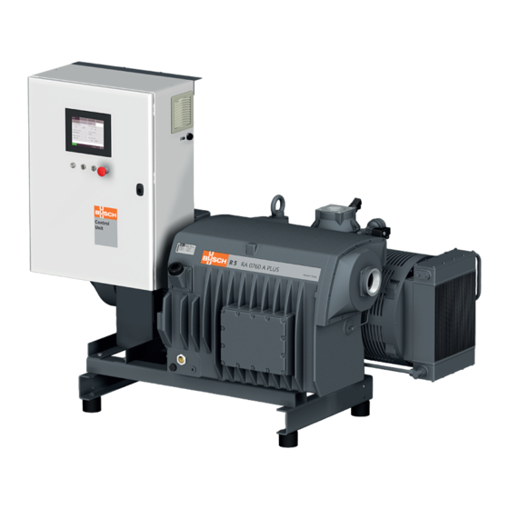
- Page 1 Instruction Manual Oil-Lubricated Rotary Vane Vacuum Pumps RA 0760 A PLUS Ateliers Busch S.A. Zone industrielle, 2906 Chevenez Switzerland 0870215096/-0001_en / Original instructions / Modifications reserved 17/05/2019...
-
Page 2: Table Of Contents
Table of Contents Table of Contents 1 Safety........................... 4 2 Product Description ..................... 5 2.1 Operating Principle....................6 2.2 Application ......................6 2.3 Standard Features....................6 2.3.1 User Interface ....................6 2.3.2 Control Unit....................6 2.3.3 Monitoring Devices..................7 2.3.4 I/O and Communication Port ..............7 2.3.5 Gas Ballast Valve..................7 2.4 Optional Accessories..................... - Page 3 Table of Contents 7.7 Monitoring ......................31 7.7.1 Operating Information................31 7.7.2 Operating Data..................33 7.7.3 History.......................36 7.7.4 Operating Curves ..................37 7.8 Dysfunction ......................39 7.8.1 Warning and Alarm Thresholds..............39 7.8.2 Warning/Alarm Acknowledgment Procedure..........40 7.9 Stop the Machine ....................41 8 Maintenance ........................ 41 8.1 Maintenance Schedule..................
-
Page 4: Safety
Safety Prior to handling the machine, this instruction manual should be read and understood. If anything needs to be clarified, please contact your Busch representative. Read this manual carefully before use and keep for future reference. This instruction manual remains valid as long as the customer does not change anything on the product. -
Page 5: Product Description
Product Description | 2 Product Description PSA1 PSA2 Air-oil heat exchanger Alarm indicator light I/O and communication port Control unit Eye bolt Exhaust filter Emergency stop switch Filter material Gas ballast valve User interface (human-machine) Suction connection Level switch (oil level) Motor (pump drive) Nameplate Oil drain plug... -
Page 6: Operating Principle
Conveying of other media leads to an increased thermal and/or mechanical load on the machine and is permissible only after a consultation with Busch. The machine is intended for the placement in a non-potentially explosive environment. The machine is designed for indoor installation, in case of outdoor installation, ask your Busch representative in order to take specific precautions. -
Page 7: Monitoring Devices
– RJ45 (Modbus) • Refer to the specific document “Pump Control Instructions, art. no.: 0870213261” for more details or contact your Busch representative. 2.3.5 Gas Ballast Valve The gas ballast valve mixes the process gas with a limited quantity of ambient air to counteract the condensation of vapour inside the machine. -
Page 8: P&Id "Piping And Instrumentation Diagram
2 | Product Description 2.5 P&ID "Piping and Instrumentation Diagram" PSA1 inlet gas MOT1 PSA2 76°C exhaust gas low oil level alarm (trip) exhaust gas Air-oil heat exchanger Coupling (fan driven by the pump shaft) Gas ballast Inlet filter (Optional) Suction connection Level switch "alarm/trip”... -
Page 9: Description Of User Interface Functions
Product Description | 2 2.7 Description of User Interface Functions The display is divided into three distinct parts. Menu tabs Information panel Bottom bar 01 .01 .2018 - 09:24 2.7.1 Menu Overview The menu consists of four main tabs with their own sub-tabs: –... -
Page 10: Bottom Bar
2 | Product Description 2.7.2 Bottom Bar The bottom bar provides different pieces of information, in particular the machine state and warning/alarm status. Warning and alarm Date and hour Help Machine state status 01 .01 .2018 - 09:24 Screen WARNING brightness RUNNING ALARM... -
Page 11: Role And User
– set the remote control and monitoring parameters, refer to the specific document "Pump Control Instructions, art. no.: 0870213261". – Role 3 ► Busch Service Only authorized people from Busch Service have this level of access rights. NOTE In case of any questions related to the machine settings: •... -
Page 12: System Settings
Warning and alarm thresholds NOTE Warning and alarm thresholds Thresholds can only be changed by Busch Service “Role 3”, see the predefined factory settings in the chapter Warning and Alarm Thresholds [► 39]. 2.7.6 Machine and Software Identification To display the machine and software identification: •... -
Page 13: Transport
Transport | 3 Transport WARNING Suspended load. Risk of severe injury! • Do not walk, stand or work under suspended loads. NOTICE In case the machine is already filled with oil. Tilting a machine that is already filled with oil can cause large quantities of oil to in- gress into the cylinder. -
Page 14: Storage
• Make sure that all provided covers, guards, hoods, etc. are mounted. If the machine is installed at an altitude greater than 1000 meters above sea level: • Contact your Busch representative, the motor should be derated or the ambient temperature limited. -
Page 15: Connecting Lines / Pipes
Connection size: – G3 If the machine is used as part of a vacuum system: • Busch recommends the installation of an isolation valve in order to prevent the oil from flowing back to the vacuum system. 5.2.2 Discharge Connection Connection size: –... -
Page 16: Filling Oil
(mineral or synthetic) written on the nameplate (NP). In case of oil type change: • Contact your Busch representative to adapt the thresholds and service intervals ac- cordingly. For oil type and oil capacity see Technical Data [► 52] and Oil [► 52]. -
Page 17: Electrical Connection
• Provide an overload protection according to EN 60204-1 for the machine. • Busch recommends installing a C-curve circuit breaker. • Make sure that the variable-frequency drive, the motor and other electrical devices will not be affected by electric or electromagnetic disturbance from the mains; if ne- cessary seek advice from Busch. -
Page 18: Wiring Diagram Control Unit
5 | Installation 5.4.1 Wiring Diagram Control Unit Internal view of the control unit: PLC1 B1 F1 Filter L1 L2 L3 Box fan Power input Customer power supply: Wire gauge according to EN 60204-1 Power supply 3L+PE 400-460V +/-10% 50/60Hz Lockable disconnect switch Overload protection C-curve - 80A... -
Page 19: Commissioning
– Warm-up / Cool-down Modes [► 28], – External Dry Contact [► 29]. Do not hesitate to contact Busch to get any further information about the configuration of your machine. • Click on the “Help” icon in the bottom bar to get the contact information of your Busch representative, see Bottom Bar [► 10]. -
Page 20: Start Up
6 | Commissioning 6.3 Start Up CAUTION During operation the surface of the machine may reach temperatures of more than 70°C. Risk of burns! • Avoid contact with the machine during and directly after operation. CAUTION Noise of running machine. Risk of damage to hearing! If persons are present in the vicinity of a non noise insulated machine over extended periods:... -
Page 21: In Operation
In Operation | 7 In Operation CAUTION During operation the surface of the machine may reach temperatures of more than 70°C. Risk of burns! • Avoid contact with the machine during and directly after operation. CAUTION Noise of running machine. Risk of damage to hearing! If persons are present in the vicinity of a non noise insulated machine over extended periods:... -
Page 22: Local/Manual
7 | In Operation 7.1.1 Local/Manual Configured by default, this mode allows to control manually the machine directly from the user interface (HMI). Control mode Local Manual Auto Remote Analog Digital Modbus 7.1.2 Local/Auto "Week Planner" The "week planner" function allows definition of a weekly schedule for starting or stop- ping the machine automatically using the current local settings. -
Page 23: Remote/Auto
Control mode Local Manual Auto Remote Analog Digital Modbus • Refer to the specific document “Pump Control Instructions, art. no.: 0870213261” for more details or contact your Busch representative. 0870215096_RA0760A_PLUS_-0001_IM_en 23 / 56... -
Page 24: Operating Mode
7 | In Operation 7.2 Operating Mode To access the operating mode menu: • Go to “OPERATIONS” > “MODE” • Stay on the first page. SYSTEM MAINTENANCE HOME OPERATIONS MODE PARAMETERS WEEK PLANNER Operating mode Speed control 60 Hz Pressure control 20 mbar NEXT 7.2.1 Speed Control... -
Page 25: Pressure Control
In Operation | 7 7.2.2 Pressure Control The pressure control mode allows the maintenance of a constant pressure level (target pressure) by automatically adapting the motor frequency. This mode is only available for “Role 2” people, see Role and User [► 11]. To switch from speed control to pressure control: •... - Page 26 7 | In Operation MAINTENANCE SYSTEM HOME OPERATIONS PARAMETERS WEEK PLANNER MODE Ecomode Time delay 10 s Ecomode pressure Restart pressure 20 mbar 100 mbar PREVIOUS NEXT • Press a value to change it. Parameter Default value Adjustment range Ecomode pressure 20 mbar 5 …...
-
Page 27: Gas Ballast Valve Control
In Operation | 7 7.4 Gas Ballast Valve Control The gas ballast valve can be controlled (open/closed position) via a simple switch button. This operation is only available for “Role 2” people. To change the state of the gas ballast valve: •... -
Page 28: Warm-Up / Cool-Down Modes
Busch scope of delivery) must be closed. An external dry contact may send a signal to pilot the isolation valve, see the chapter Ex- ternal Dry Contact [► 29] or contact your Busch representative for any further inform- ation. -
Page 29: Conveying Condensable Vapours
In Operation | 7 7.5.1 Conveying Condensable Vapours Water vapour within the gas flow is tolerated within certain limits. The conveyance of other vapours shall be agreed upon with Busch. If condensable vapours are to be conveyed: • Open the isolation 30 minutes •... - Page 30 7 | In Operation • Enable or disable the external dry contact. Once the external dry contact enabled, its state is visible: External dry contact state Contact open Contact closed Below the chronogram of the external dry contact: Time delay Pump Pump Pump...
-
Page 31: Monitoring
In Operation | 7 7.7 Monitoring 7.7.1 Operating Information This display “HOME” > “MAIN” corresponds to the principal menu and is automatically loaded when the machine is started. It allows the reading of the principal operating informa- tion. HOME MAINTENANCE SYSTEM OPERATIONS MAIN... - Page 32 7 | In Operation Next service in: Indicates the number of operating hours remaining before the next maintenance, see Maintenance Schedule [► 41]. 32 / 56 0870215096_RA0760A_PLUS_-0001_IM_en...
-
Page 33: Operating Data
In Operation | 7 7.7.2 Operating Data This display “HOME” > “MONITORING” allows the reading operating values, it is di- vided into three different pages. PAGE 1 HOME OPERATIONS MAINTENANCE SYSTEM ALARM MAIN MONITORING > Gas-ballast valve Exhaust pressure Open 84 mbar Instant absorbed power Mean absorbed power... - Page 34 7 | In Operation PAGE 2 HOME OPERATIONS MAINTENANCE SYSTEM ALARM MAIN MONITORING Oil temperature Exhaust gas temperature 82 °C Oil level Motor frequency 60 Hz PREVIOUS NEXT Oil temperature: Indicates the oil temperature, in case of a too high temperature a warning or an alarm occurs, see Dysfunction [► 39].
- Page 35 In Operation | 7 PAGE 3 HOME OPERATIONS MAINTENANCE SYSTEM MAIN MONITORING ALARM Energy consumption since last reset Reset energy consumption (Press button 5s) 921 kWh Energy consumption total Motor start counter 5412 kWh PREVIOUS NEXT Energy consumption since last reset: Indicates the energy consumption in kWh since the last reset.
-
Page 36: History
7 | In Operation 7.7.3 History This display “MAINTENANCE” > “HISTORY” shows the history of: – Events ► Parameter changes, function activation, etc… – Alarms ► Alarm signals from sensors – Warnings ► Warning signals from sensors – Service ► Service tasks completed It is possible to filter the type of message by selecting a specific tab. -
Page 37: Operating Curves
In Operation | 7 7.7.4 Operating Curves This display “MAINTENANCE” > “TREND” shows the trend curve of certain operating values. It offers the possibility to change the time lapse and the curve of four different operating values. MAINTENANCE SYSTEM HOME OPERATIONS HISTORY SERVICE... - Page 38 7 | In Operation If more than one curve type is selected, a matching scale appears to the right of the graph. MAINTENANCE SYSTEM HOME OPERATIONS HISTORY SERVICE TREND Power consumption Oil temperature <=> 10kW <=> 100°C Select curve -5min 08.40.24 -15min -10min...
-
Page 39: Dysfunction
In Operation | 7 7.8 Dysfunction 7.8.1 Warning and Alarm Thresholds When the machine has reached the limit threshold of an operating value, which is pre- defined in the system, a signal is sent and visible in the bottom bar. There are two signal levels: –... -
Page 40: Warning/Alarm Acknowledgment Procedure
NOTE Threshold values are preset with the factory settings. However, depending on the applic- ation, it is possible to adjust the threshold values only after Busch approval. Threshold changes are only available for "Role 3" people. 7.8.2 Warning/Alarm Acknowledgment Procedure... -
Page 41: Stop The Machine
If an inlet filter is installed: • Check the inlet filter cartridge, change it if necessary. • Contact Busch for an inspection. Every 5 years If required, overhaul the machine. * Service interval for synthetic oil, shorten the interval when using mineral oil, contact... -
Page 42: Oil Level Inspection
8 | Maintenance To visualise information about remaining hours: • Go to “MAINTENANCE” > “SERVICE”. • Check when the maintenance tasks have to be performed and how long the machine has operated since the first commissioning or last maintenance task. MAINTENANCE SYSTEM HOME... -
Page 43: Oil And Oil Filter Change
(mineral or synthetic) written on the nameplate (NP). In case of oil type change: • Contact your Busch representative to adapt the thresholds and service intervals ac- cordingly. 1x o-ring, part no.: 0486 000 505... - Page 44 8 | Maintenance Busch genuine spare parts 1x oil filter (OF), part no.: 0531 000 005 Unscrew the oil filter if necessary use an oil filter wrench For oil type and oil capacity see Technical Data [► 52] and Oil [► 52].
-
Page 45: Exhaust Filter Change
8.4 Exhaust Filter Change 8x exhaust filter (EF) 6 mm hex key extract filter material (FM) 6 mm hex key Busch genuine spare parts, Max. admissible torque: 21 Nm 8x exhaust filter (EF), part no.: 0532 140 160 O-ring 1x filter material (FM) part no.: 0537 000 042... -
Page 46: Air Heat Exchanger Cleaning
• Decontaminate the machine as much as possible and state the contamination status in a ‘Declaration of Contamination’. Busch will only accept machines that come with a completely filled in and legally binding signed ‘Declaration of Contamination’. (Form downloadable from www.buschvacuum.com) -
Page 47: Decommissioning
Use of non-Busch genuine spare parts. Risk of premature failure! Loss of efficiency! • The exclusive use of Busch genuine spare parts and consumables is recommended for the correct functioning of the machine and to validate the warranty. Spare parts kit Description Part no. -
Page 48: Troubleshooting
12 | Troubleshooting 12 Troubleshooting DANGER Carry out any work on the control unit and motor. Risk of electrical shock! • Electrical installation work must only be executed by qualified personnel. CAUTION Hot surface. Risk of burns! • Prior to any action requiring touching the machine, let the machine cool down first. NOTICE Variable-frequency drive maintenance. - Page 49 (EF) and the o-rings. The float valve (FV) does • Check float valve and the not work properly. oil return line, repair it if necessary (contact Busch). Abnormal oil consumption. Oil leaks. • Replace seals (contact Busch). The float valve (FV) does •...
- Page 50 (pressure dersized for the application. work. control mode only). Leaks or pressure drops in • Ask Busch for advice. the pipework upstream the suction connection. Communication problems A wire is cut or not connec- • Check the wiring between when the machine is re- ted.
- Page 51 Troubleshooting | 12 Table 2 Message Possible Cause Remedy Fan breaker The circuit breaker of the • Refer to schematic and (alarm) cooling fan has tripped. reset the breaker. VFD breaker The circuit breaker of the • Refer to schematic and (alarm) variable frequency drive has reset the breaker.
-
Page 52: Technical Data
0831 168 359 0831 168 353 In case of unfavourable ambient temperature, other oil viscosities may be used. Please consult your Busch repre- sentative for more details. To know which oil has been filled in the machine, please refer to the nameplate (NP). -
Page 53: Eu Declaration Of Conformity
This Declaration of Conformity and the CE-mark affixed to the nameplate are valid for the machine within the Busch scope of delivery. This Declaration of Conformity is issued under the sole responsibility of the manufacturer. When this machine is integrated into a superordinate machinery the manufacturer of the superordinate machinery (this can be the operating company, too) must conduct the conformity assessment process for the superordinate machine or plant, issue the Declaration of Conformity for it and affix the CE-mark. - Page 54 Note...
- Page 55 Note...
- Page 56 Colombia Korea South Africa www.buschvacuum.com/co www.buschvacuum.com/kr www.buschvacuum.com/za info@buschvacuum.co busch@busch.co.kr info@busch.co.za Czech Republic Malaysia Spain www.buschvacuum.com/cz www.busch.com.my www.buschvacuum.com/es info@buschvacuum.cz busch@busch.com.my contacto@buschiberica.es Denmark Mexico Sweden www.buschvacuum.com/dk www.buschvacuum.com/mx www.buschvacuum.com/se info@busch.dk info@busch.com.mx info@busch.se www.buschvacuum.com 0870215096/-0001_en / © Ateliers Busch S.A.
Need help?
Do you have a question about the R 5 Series and is the answer not in the manual?
Questions and answers