
Related Manuals for Bender COM461MT


Summary of Contents for Bender COM461MT
- Page 1 Manual COM461MT BMS-Ethernet gateway for the connection of Bender devices with BMS support to Ethernet (TCP/IP) using the Modbus/TCP protocol Software version: D402 V1.0x COM461MT_D00011_00_M_XXEN/05.2013...
- Page 2 Bender GmbH & Co. KG Londorfer Str. 65 • 35305 Grünberg • Germany Postfach 1161 • 35301 Grünberg • Germany Tel.: +49 6401 807-0 Fax: +49 6401 807-259 E-Mail: info@bender-de.com Web: http://www.bender-de.com © Bender GmbH & Co. KG All rights reserved.
-
Page 3: Table Of Contents
Properties ......................11 Possible applications ................... 12 4. Installation, connection and commissioning ........... 13 Preliminary considerations ................ 13 COM461MT on the internal BMS bus ............. 14 Installing the device ..................16 Connecting the device ................17 Commissioning ....................19 4.5.1 Determining address data ................. 22 5. - Page 4 Modbus responses ..................26 Structure of the exception code .............. 27 Modbus address structure for BMS devices ......... 27 7. Modbus process image in the memory of the COM461MT ....29 Requesting data ..................... 29 7.1.1 Modbus function code ................29 7.1.2 How are the memory areas organised? ..........
- Page 5 Table of Contents Ordering data ....................62 9. Troubleshooting .................... 63 Damage in transit ..................63 Malfunctions ....................63 9.2.1 What should be checked? ................63 9.2.2 Where do you go to get help? ..............64 INDEX ........................65 COM461MT_D00011_00_M_XXEN/05.2013...
-
Page 7: Making Effective Use Of This Document
1. Making effective use of this document 1.1 How to use this manual This operating manual is aimed at qualified experts in electrical en- gineering and communications technology! To make it easier for you to understand and revisit certain sections of text and instructions in the manual, we have used symbols to identify important in- structions and information. -
Page 8: Quick Reference Guide
Data access using Modbus/TCP protocol: Describes how to send requests to the Modbus/TCP server in the COM461MT and how the responses are to be interpreted Modbus process image in the COM461MT's memory: In this chapter, the representation of BMS data on Modbus/TCP struc-... -
Page 9: Safety Instructions
European standard EN 50110 can be used as a guide. 2.2 Intended use The BMS-Ethernet gateway COM461MT connects the serial BMS bus to Ethernet TCP/IP networks. The gateway converts alarms, measured values and statuses from the BMS bus to the Modbus/TCP protocol. This allows connec- tion to Modbus networks. -
Page 10: Address Setting And Termination
Safety instructions 2.3 Address setting and termination In order to ensure proper functioning of the BMS-Ethernet gateway COM461MT, correct address assignment and termination of the BMS bus is of utmost importance. Assigning addresses that are already used by existing de- vices in the BMS or TCP/IP networks concerned may cause serious malfunctions. -
Page 11: Product Description
3.2 A short description The BMS-Ethernet gateway COM461MT contains a Modbus/TCP server that converts the BMS data for a Modbus client. A web server makes it possible to configure the COM461MT (see “Commis- sioning” on page 19). Ethernet-TCP/IP interface: The coupling is performed via the internal Layer-2 switch. Two Ethernet ports are available. -
Page 12: Possible Applications
Product description 3.4 Possible applications Usage of professional data display programs by converting the BMS data to the Modbus/TCP protocol Observing and analysing Bender products that support communica- tion, such as RCMS, EDS and MEDICS® systems COM461MT_D00011_00_M_XXEN/05.2013... -
Page 13: Installation, Connection And Commissioning
5. Are suitable PC hardware and software available for commissioning? - Minimum system requirements: 1.6-GHz processor/512 MB RAM / Windows XP/Vista/7/Web browser. For initial connection, the basic configuration of the COM461MT is to be un- dertaken outside the installation, depending on the specific situation. COM461MT_D00011_00_M_XXEN/05.2013... -
Page 14: Com461Mt On The Internal Bms Bus
4.2 COM461MT on the internal BMS bus Bender systems such as EDS46x/49x, RCMS46x/49x and MEDICS communi- cate with each other via the Bender measuring device interface BMS. The BMS-Ethernet gateway COM461MT provides the coupling between the BMS bus and TCP/IP networks. The internal Modbus/TCP server in the COM461MT communicates with the Modbus/TCP client via these networks. - Page 15 Installation, connection and commissioning COM461MT Fig. 4.1: Block diagram of a coupling between an internal BMS bus and TCP/IP networks COM461MT_D00011_00_M_XXEN/05.2013...
-
Page 16: Installing The Device
Installation, connection and commissioning 4.3 Installing the device Possible methods of mounting: DIN rail mounting Screw mounting with 2 x M4 (dimension diagram on page 61) When installing the device, please take into considera- tion that the device is only to be used in locations that are protected from unauthorised entry! This can be installation in a switch cabinet, for example. -
Page 17: Connecting The Device
– For use in pollution degree 2 environments – Only 60/75 °C copper wires are to be used – Tightening torque for terminals 0.5…0.6 Nm Connect the terminals and sockets on the COM461MT according to the wiring diagram. A1 A2... - Page 18 Installation, connection and commissioning Terminal Description Connection to the supply voltage, 6 A fuse recommended, A1, A2 two-pole fuses should be used on IT systems. For UL and CSA applications, it is mandatory to use 5 A fuses Two connections for connection to a personal computer or to ETH1, the local network (hub, switch, router);...
-
Page 19: Commissioning
Installation, connection and commissioning 4.5 Commissioning 1. Apply the supply voltage to the COM461MT. The green "ON" LED illu- minates. 2. Connect the COM461MT to a PC and open a web browser. 3. Enter the IP address for the COM461MT (factory setting 192.168.0.254). - Page 20 4. Make the necessary settings. Make a note of the modified settings: Para- Factory Modified Meaning meter setting setting IP address IP address of the 192.168.0.254 COM461MT Subnet Subnet mask of the 255.255.0.0 COM461MT Address on the internal address BMS bus Modbus Enable or disable control control...
- Page 21 Installation, connection and commissioning Para- Factory Modified Meaning meter setting setting Summer- Select summer time set- time ting: Off = Function disabled DST = Automatic switchover, USA, CDN CEST = Automat. switcho- ver, Central Europe On = Set time zone + 1 h Date Date Time...
-
Page 22: Determining Address Data
Determining address data The IP address and subnet mask set must be known for the operation of the COM461MT. If these data have been changed without making a note of the modified address data, the following options are available: Enter NetBIOS name in the web browser: "http://com461mt" or ... -
Page 23: The Bms-Ethernet Gateway Com461Mt
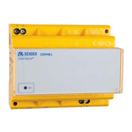
5. The BMS-Ethernet gateway COM461MT 5.1 Display and operating elements COM461 COMTRAXX® Fig. 5.1: COM461MT front panel "ON" LED lights when supply voltage is applied Ron/off (beside terminals A, B) Switch for terminating the BMS bus. When the device is installed at the end of the bus, set the terminating switch to "on". - Page 24 The BMS-Ethernet gateway COM461MT COM461MT_D00011_00_M_XXEN/05.2013...
-
Page 25: Data Access Using Modbus/Tcp Protocol
6. Data access using Modbus/TCP protocol Requests are sent to the Modbus/TCP server in the COM461MT using function code FC4 (read input register). The server generates a function-related re- sponse and sends it to the Modbus client. 6.1 Exception code If a request cannot be answered for whatever reason, the server sends a so- called exception code with which possible faults can be narrowed down. -
Page 26: Modbus Requests
The required words of the process image can be read from the input registers in the COM461MT using the function code FC4. For this purpose, the start ad- dress and the number of registers to be read need to be entered. -
Page 27: Structure Of The Exception Code
Data access using Modbus/TCP protocol Byte Name Example Byte 9, 10 Value register 0 0x1234 (fictitious value) Byte 11, 12 Value register 1 0x2345 (fictitious value) 6.4 Structure of the exception code Byte Name Example … … … Byte 7 MODBUS function code 0x84 Byte 8... - Page 28 Data access using Modbus/TCP protocol COM461MT_D00011_00_M_XXEN/05.2013...
-
Page 29: Modbus Process Image In The Memory Of The Com461Mt
7.1.1 Modbus function code The memory in the COM461MT can be read using the Modbus function 4 "Read input registers". The volume of the data requested depends on the number of bytes selected in the Modbus client used. Up to 125 words (0x7D) can be read with a single request. -
Page 30: Memory Scheme Of The Process Image
Modbus process image in the memory of the COM461MT The assignment of the memory addresses and the associated memory con- tent is described below. 7.2 Memory scheme of the process image 7.2.1 BMS device address assignment on the Modbus As illustrated in the table, the Modbus start address for the respective process image is derived from the BMS device address. -
Page 31: Memory Scheme Of An Individual Bms Device
Modbus process image in the memory of the COM461MT 7.2.2 Memory scheme of an individual BMS device BMS devices can feature various types of analogue and/or digital channels. Please take into consideration that there are device-specific differences: BMS devices usually feature 12 channels ... - Page 32 Modbus process image in the memory of the COM461MT Memory image of a BMS device ------------------------- Device type ------------------------- ---- Timestamp ---- C D R. Channel 1 Channel 2 Channel 3 Channel 4 Channel 5 Channel 6 Channel 7 Channel 8...
-
Page 33: Device Name
Modbus process image in the memory of the COM461MT R. R. R. R. R. R. R. R. R. R. R. R. R. R. R. R. R. R. R. R. R. R. R. R. R. R. R. R. R. R. R. R. -
Page 34: Timestamp
Modbus process image in the memory of the COM461MT 7.2.4 Timestamp Word 0x0A 0x0B 0x0C 0x0D HiByte LoByte HiByte LoByte HiByte LoByte HiByte LoByte Year Month Hour Minute Second served The timestamp is set according to a datagram received from a transmitting device. -
Page 35: Channels 1 To 32 With Analogue And/Or Digital Values
Modbus process image in the memory of the COM461MT 7.2.6 Channels 1 to 32 With analogue and/or digital values Word 0x00 0x01 0x02 0x03 HiByte LoByte HiByte LoByte HiByte LoByte HiByte LoByte Channel Floating point value (Float) AT&T R&U description Every analogue BMS device channel can contain alarm messages, operating messages, measured values, test messages and descriptive text. -
Page 36: A&T = Alarm Type And Test Type (Internal/External)
Modbus process image in the memory of the COM461MT 7.2.6.2 A&T = Alarm type and test type (internal/external) Meaning No alarm Prewarning Device error Reserved Alarm (yellow LED), e.g. insulation fault Alarm (red LED) Reserved … … … Reserved Reserved... -
Page 37: R&U = Range And Unit
Modbus process image in the memory of the COM461MT 7.2.6.3 R&U = Range and unit Meaning Invalid (init) No unit Ω Baud °C °F Second Minute Hour Month X … … … … … Reserved CODE Reserved X … … … … …... - Page 38 Modbus process image in the memory of the COM461MT Meaning True value True value is smaller True value is larger Invalid value The unit is coded in the bits 0 to 4. The bits 6 and 7 describe the range of validity of a value. Bit 5 is reserved.
-
Page 39: Channel Description
Modbus process image in the memory of the COM461MT 7.2.6.4 Channel description A code with the associated descriptive text is available for each channel. The table above only shows an extract from the texts. For a complete list of the available codes or texts refer to page 45. -
Page 40: Channel 33 To 64
Modbus process image in the memory of the COM461MT 7.2.6.5 Channel 33 to 64 Meaning No alarm Prewarning Device error Reserved Alarm (yellow LED), e.g. insulation fault Alarm (red LED) Reserved … … … Reserved Reserved No test Internal test External test The BMS channels 33 to 64 only provide digital information. -
Page 41: Reference Data Records Of The Process Image
7.3 Reference data records of the process image To make it easier to check the configuration and the Modbus/TCP data access to BMS devices, COM461MT provides a reference data record at the virtual BMS address 0. A real BMS device cannot have BMS address 0! Address 0 only serves to simulate data access. -
Page 42: Reference Value On Channel 1
Modbus process image in the memory of the COM461MT The start addresses provide the following reference values: 0x0000: TEST (device type) 0x000E: 1 (common alarm, LSB of the high byte is set) 0x0010: 230 V undervoltage (reference value on channel 1) ... -
Page 43: Reference Value On Channel 2
Modbus process image in the memory of the COM461MT 7.3.3 Reference value on channel 2 The following reference value is stored in this channel: 12.34 A Word 0x14 0x15 0x16 0x17 HiByte LoByte HiByte LoByte HiByte LoByte HiByte LoByte 0x41... - Page 44 Modbus process image in the memory of the COM461MT Word 1 Word 2 Floating Hex value point sequence value Byte 1 Byte 2 Byte 3 Byte 4 CORRECT 12.34 Word swap- 4.066E+29 ping Byte swapping 3098.27 Word and byte -5.21E-17 swapping COM461MT_D00011_00_M_XXEN/05.2013...
-
Page 45: Channel Descriptions For The Process Image
Modbus process image in the memory of the COM461MT 7.4 Channel descriptions for the process image Measured value, description Value Note alarm message, operating message 1 (0x01) Insulation fault 2 (0x02) Overload 3 (0x03) Overtemperature 4 (0x04) Failure line 1... - Page 46 Modbus process image in the memory of the COM461MT Measured value, description Value Note alarm message, operating message 14 (0x0E) Failure nitrogen 15 (0x0F) Failure CO2 16 (0x10) Insulation UPS Insulation fault UPS 17 (0x11) Overload UPS 18 (0x12) Converter UPS...
- Page 47 Modbus process image in the memory of the COM461MT Measured value, description Value Note alarm message, operating message Failure UPS Failure additional power 27 (0x1B) supply 28 (0x1C) Ins.safety supply 29 (0x1D) Fail.N conductor Short distr.panel Short-circuit distribution 30 (0x1E)
- Page 48 Modbus process image in the memory of the COM461MT Measured value, description Value Note alarm message, operating message Failure UPS Battery supported safety 40 (0x28) power supply 41 (0x29) 66 (0x42) 67 (0x43) Function test by: Date 68 (0x44) Service by:...
- Page 49 Modbus process image in the memory of the COM461MT Measured value, description Value Note alarm message, operating message 77 (0x4D) Undervoltage 78 (0x4E) Overvoltage 79 (0x4F) Frequency Measured value in Hz 80 (0x50) 81 (0x51) Asymmetry 82 (0x52) Capacitance Measured value in F...
- Page 50 Modbus process image in the memory of the COM461MT Measured value, description Value Note alarm message, operating message Service code Information about service 97 (0x61) intervals Mains power connec- 101 (0x65) tion 102 (0x66) Earth connection 103 (0x67) Short CT...
- Page 51 Modbus process image in the memory of the COM461MT Measured value, description Value Note alarm message, operating message 110 (0x6E) 111 (0x6F) No address: Failure BMS device 112 (0x70) 113 (0x71) Failure K1/Q1 Failure contactor K1/Q1 114 (0x72) Failure K2/Q2...
- Page 52 Modbus process image in the memory of the COM461MT Measured value, description Value Note alarm message, operating message 126 (0x7E) Fault 127 (0x7F) Fault 128 (0x80) No Master 129 (0x81) Device error 130 (0x82) 131 (0x83) Fault RS-485 132 (0x84)
- Page 53 Modbus process image in the memory of the COM461MT Measured value, description Value Note alarm message, operating message Address collision BMS address has been 141 (0x8D) assigned several times 142 (0x8E) Invalid address 143 (0x8F) Several masters 144 (0x90) No menu access...
- Page 54 Modbus process image in the memory of the COM461MT Measured value, description Value Note alarm message, operating message 209 (0xD1) 210 (0xD2) Line AV on 211 (0xD3) Line SV on 212 (0xD4) Line UPS on 213 (0xD5) Channel disabled SwitchBackLock...
- Page 55 Modbus process image in the memory of the COM461MT To convert the data of parameters, you will need data type descriptions. Text representation is not necessary in this case. Value Description of parameters: Parameter/measured value invalid. 1023 (0x3FF) The menu item for this parameter is not displayed...
- Page 56 Modbus process image in the memory of the COM461MT Value Description of parameters: 1009 (0x3F1) Factor multiplication [*] 1008 (0x3F0) Factor division [/] 1007 (0x3EF) Baud rate COM461MT_D00011_00_M_XXEN/05.2013...
-
Page 57: Modbus Control Commands
Modbus process image in the memory of the COM461MT 7.5 Modbus control commands Commands can be sent to BMS devices by an external application (e.g. data display software). Control via Modbus can be enabled or disabled on the "Settings" browser menu. - Page 58 Modbus process image in the memory of the COM461MT Control commands for the internal BMS bus Register Register Register Register Function Channel Comma 1-150 Test Isometer 1-150 Test changeover device PRC 1-150 Start automatic test changeover 1->2, end after time...
-
Page 59: Technical Data
8. Technical data ( )* = Factory setting 8.1 Tabular data Insulation co-ordination according to IEC 60664-1 Rated voltage..............................AC 250 V Rated impulse voltage/pollution degree......................4 kV/3 Supply voltage Supply voltage ..........................See ordering data Frequency range ..........................See ordering data Power consumption ..........................See ordering data LED indicators 2 x Ethernet ETH1, ETH2 act/link.. - Page 60 Technical data General data EMC ................................EN 61326-1 Climate classes acc. to IEC 60721: Stationary use ................................3K5 Transport .................................. 2K3 Long-term storage ..............................1K4 Operating temperature .......................... -10 …+55 °C Mechanical conditions acc. to IEC 60721: Stationary use ................................3M4 Transport .................................
-
Page 61: Dimension Diagram
Technical data 8.2 Dimension diagram 8.3 Standards, approvals, certifications For information on UL applications refer to page 17. Other interface protocols Connection to control system and/or PLC via OPC, BACnet or other protocols on request. COM461MT_D00011_00_M_XXEN/05.2013... -
Page 62: Ordering Data
Technical data 8.4 Ordering data Power Supply voltage/ Item Type con- frequency range sumption COM461MT AC/DC 76…276 V */ 3.5…40 VA/ UL listed: B 9506 BMS- AC 42…460 Hz/DC 2.4 W Approval 1021 Ethernet available For UL applications: gateway AC = 76…250 V, Lloyds 40…150 mA,... -
Page 63: Troubleshooting
Bender GmbH & Co.KG Londorfer Strasse 65 35305 Gruenberg, Germany +49 6401 807-0 9.2 Malfunctions If the COM461MT causes malfunctions in the connected networks, please re- fer to this operating manual. 9.2.1 What should be checked? Check whether … The device is supplied with the correct supply voltage ... -
Page 64: Where Do You Go To Get Help
Where do you go to get help? If, despite thorough study of the technical manual and intensive trouble- shooting in your installation, you cannot rectify the fault related to the BMS- Ethernet gateway COM461MT, please contact our Service department: Tel.: +49 6401 807-760 or 0700BENDERHELP... -
Page 65: Index
INDEX Address assignment 10 Malfunctions 63 Application with internal BMS bus 15 Measured value descriptions for the process image, list 45 Memory image of a BMS device 32 BMS bus 14 Memory scheme of the process image 30 BMS device address assignment on the Modbus Modbus 30 - Address structure for BMS devices... - Page 66 Scope of supply 11 Settings 19 Support 64 Technical data 59 Termination 10 Termination of the BMS bus 18 Troubleshooting 63 UL applications, restrictions 17 Using this manual 7 Wiring diagram 17 Work activities on electrical installations 9 COM461MT_D00011_00_M_XXEN/05.2013...
- Page 68 D0001100MXXEN Bender GmbH & Co. KG Londorfer Str. 65 • 35305 Grünberg • Germany Postfach 1161 • 35301 Grünberg • Germany Tel.: +49 6401 807-0 Fax: +49 6401 807-259 E-Mail: info@bender-de.com Web: http://www.bender-de.com...
Need help?
Do you have a question about the COM461MT and is the answer not in the manual?
Questions and answers