Advertisement
Quick Links
sauder.com
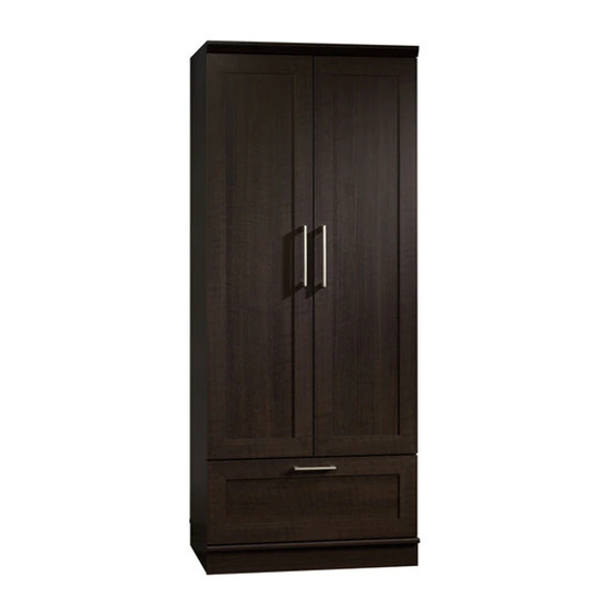
Wardrobe/Storage Cabinet
HomePlus Collection | Model 411312
Need help? Visit Sauder.com to view video assembly tips or chat with a live rep.
Prefer the phone? Call 1-800-523-3987.
Share your journey!
Store behind
closed doors.
NOTE: THIS INSTRUCTION
BOOKLET CONTAINS IMPORTANT
SAFETY INFORMATION.
PLEASE READ AND KEEP FOR
FUTURE REFERENCE.
English pg 1-22
Français pg 23-25
Español pg 26-28
Lot # 387972
01/27/16
Purchased: __________________
Be sure to give us a ring before
making any returns. 1-800-523-3987
Advertisement

Subscribe to Our Youtube Channel
Related Manuals for Sauder HomePlus 411312


Summary of Contents for Sauder HomePlus 411312
- Page 1 HomePlus Collection | Model 411312 NOTE: THIS INSTRUCTION BOOKLET CONTAINS IMPORTANT SAFETY INFORMATION. Need help? Visit Sauder.com to view video assembly tips or chat with a live rep. PLEASE READ AND KEEP FOR FUTURE REFERENCE. Prefer the phone? Call 1-800-523-3987.
-
Page 2: Table Of Contents
SHELF (1) TOP MOLDING (1) BOTTOM (1) DOOR (2) LARGE BALLAST (2) ADJUSTABLE SHELF (1) RIGHT DRAWER SIDE (1) SMALL BALLAST (2) FRONT SKIRT (1) LEFT DRAWER SIDE (1) SIDE SKIRT (2) D175 DRAWER BACK (1) Page 2 411312 www.sauder.com/services... -
Page 3: Part Identifi Cation
Now you know Part Identifi cation our ABCs. D175 D983 www.sauder.com/services 411312 Page 3... -
Page 4: Hardware Identifi Cation
Use of tip-over restraints may only reduce, but not eliminate, the risk of tip-over. This is a permanent label. Do not attempt to remove! METAL RUBBER 04/10 332296 PIN - 4 SLEEVE - 4 (Refer to Step 16 for proper location and application) Page 4 411312 www.sauder.com/services... - Page 5 BLACK 7/8" MACHINE SCREW - 6 BLACK 9/16" LARGE HEAD SCREW - 7 BLACK 9/16" WAFER HEAD SCREW - 4 BLACK 1/2" FLAT HEAD SCREW - 12 NAIL - 52 GOLD 5/16" FLAT HEAD SCREW - 8 www.sauder.com/services 411312 Page 5...
- Page 6 fl oor. Scan this QR code or go to this address: http://qr.sauder.com/?ID=1378 To begin assembly, push a SAUDER TWIST-LOCK® å to watch a video on how to assemble your unit. FASTENER (U) into the large holes in the TOP (C) and SHELF (F).
- Page 7 Use two BLACK 9/16" LARGE HEAD SCREWS (QQ). BLACK 9/16" LARGE HEAD SCREW (2 used for the ROD HANGERS) Long fi nished edge Roller end Long fi nished edge Roller end GOLD 5/16" FLAT HEAD SCREW (4 used for the CABINET RAILS) www.sauder.com/services 411312 Page 7...
-
Page 8: Back
Step 3 Fasten the LEFT END (B) to the TOP (C) and SHELF (F). å ® How to use the SAUDER TWIST-LOCK FASTENER Tighten four TWIST-LOCK® FASTENERS. 1. Insert the dowel end of the FASTENER into the hole of the adjoining part. - Page 9 Fasten the RIGHT END (A) to the TOP (C) and SHELF (F). å Tighten four TWIST-LOCK® FASTENERS. Fasten the TOP MOLDING (P) to the TOP (C). Tighten two å TWIST-LOCK® FASTENERS. Curved edge Long fi nished edge www.sauder.com/services 411312 Page 9...
- Page 10 Fasten the BOTTOM (D2) to the ENDS (A and B). Use four å BLACK 1-7/8" FLAT HEAD SCREWS (OO). Rounded edge fi n i s h r f a BLACK 1-7/8" FLAT HEAD SCREW (4 used in this step) Page 10 411312 www.sauder.com/services...
- Page 11 To lower a corner, turn the ADJUSTABLE GLIDE clockwise. Insert the ADJUSTABLE (4 used) SHELF (I) between the ENDS (A and B) before turning over the unit. BLACK 9/16" WAFER HEAD SCREW (4 used in this step) www.sauder.com/services 411312 Page 11...
- Page 12 Fasten the BALLASTS (VV and WW) to the BOTTOM (D2). å Use two BLACK 3" PAN HEAD SCREWS (84S). These holes must line up over the SHELF (F). BLACK 3" PAN HEAD SCREW (2 used in this step) Page 12 411312 www.sauder.com/services...
- Page 13 Step 8 Fasten three HINGES (Z) to each DOOR (H). Use twelve å BLACK 1/2" FLAT HEAD SCREWS (SS). BLACK 1/2" FLAT HEAD SCREW (12 used in this step) www.sauder.com/services 411312 Page 13...
-
Page 14: Top
Fasten a LARGE PULL (GG) to the DOOR (H). Use two å BLACK 7/8" MACHINE SCREWS (PP). Repeat this step for the other door. å Stop Mounting screw Hinge BLACK 7/8" MACHINE SCREW (4 used for the PULLS) Page 14 411312 www.sauder.com/services... - Page 15 To adjust the DOORS in or out (depth), loosen the mounting screw one turn å and move the DOORS in or out, as needed. Tighten the mounting screw after making adjustments. Mounting screw (depth) Adjusting screw (horizontal) (vertical adjustment) www.sauder.com/services 411312 Page 15...
- Page 16 Step 11 Turn a CAM SCREW (8F) into the DRAWER FRONT (L). å Push a HIDDEN CAM (1F) into the DRAWER BRACE (M65). å Do not tighten the HIDDEN CAM in this step. Arrow Page 16 411312 www.sauder.com/services...
- Page 17 BLACK 9/16" LARGE HEAD SCREW (4 used in this step) With the palm of your hand, tap the DRAWER BOTTOM Groove down into the groove. D983 f a c s u r n i s h U n fi www.sauder.com/services 411312 Page 17...
- Page 18 DRAWER BRACE (M65). Use fi ve BLACK 1-9/16" FLAT HEAD SCREWS (30S). Surface with HIDDEN CAM Start each screw a few turns before completely tightening any of them. BLACK 1-9/16" FLAT HEAD SCREW (5 used in this step) D175 Page 18 411312 www.sauder.com/services...
- Page 19 Fasten the PULL (HH) to the DRAWER FRONT (L). Use two å BLACK 7/8" MACHINE SCREWS (PP). Roller end BLACK 7/8" MACHINE SCREW (2 used for the PULL) Roller end GOLD 5/16" FLAT HEAD SCREW (4 used in this step) www.sauder.com/services 411312 Page 19...
- Page 20 Insert the METAL PINS into the hole locations of your choice in the ENDS (A and B). Set the ADJUSTABLE SHELF (I) onto the METAL PINS. Set the ROD (V) onto the ROD HANGERS on å the ENDS (A and B). (4 used) Page 20 411312 www.sauder.com/services...
-
Page 21: Drawer Front
-Never open more than one drawer at a time. -If equipped with a drawer interlock system, do not defeat or remove it. Use of tip-over restraints may only reduce, but not eliminate, the risk of tip-over. www.sauder.com/services 411312 Page 21... - Page 22 BLACK 1-7/8" FLAT HEAD SCREW (1 used into a stud in your wall) No load BLACK 9/16" LARGE HEAD SCREW (1 used into the top of your unit) 25 lbs. 40 lbs. 50 lbs. 35 lbs. Page 22 411312 www.sauder.com/services...
- Page 23 EXTRÉMITÉ DROITE ...........1 SUPPORT DE TRINGLE ..........2 pour future référence. EXTRÉMITÉ GAUCHE ........1 EXCENTRIQUE ESCAMOTABLE ......1 Pour contacter Sauder DESSUS ................1 VIS D'EXCENTRIQUE ..........1 en ce qui concerne cet élément, faire référence DESSOUS ..............1 CHARNIÈRE ..............6 au numéro de lot et...
- Page 24 Pour commencer l'assemblage, enfoncer une FIXATION TWIST-LOCK® SAUDER (U) dans les gros trous du DESSUS (C) et de la TABLETTE (F). Veiller à avoir des marges égales le long des quatre chants de l'ARRIÈRE (E). Si besoin est, enfoncer sur les coins opposés de l'élément pour s'assurer d'être «...
- Page 25 Ceci complète l'assemblage. Pour nettoyer, utiliser l'encaustique pour meubles les trous nº 2 et nº 4. préférée ou un chiff on humide. Essuyer. Fixer la POIGNÉE (HH) au DEVANT DE TIROIR (L). Utiliser deux VIS NOIRES À MÉTAUX 22 mm (PP). www.sauder.com/services 411312 Page 25...
- Page 26 BIELA DE EXCÉNTRICO ..............1 EXTREMO IZQUIERDO ............1 pour future référence. BISAGRA ..................6 Pour contacter Sauder PANEL SUPERIOR ..............1 MÉNSULA DE SEGURIDAD ..........1 en ce qui concerne cet FONDO .................... 1 élément, faire référence TOPE DE PUERTA ..............
- Page 27 Cuidadosamente voltee la unidad para que repose sobre los bordes delanteros. Para comenzar el ensamblaje, empuje un SUJETADOR TWIST-LOCK® SAUDER (U) Desdoble el DORSO (E) y colóquelo sobre la unidad. dentro de los agujeros grandes del PANEL SUPERIOR (C) y del ESTANTE (F).
- Page 28 Fije el TIRADOR (HH) a la CARA DE CAJÓN (L). Utilice dos TORNILLOS NEGROS Esto completa el ensamblaje. Limpie con su pulimento para muebles preferido o un paño PARA METAL de 22 mm (PP). húmedo. Seque con un paño. Page 28 411312 www.sauder.com/services...
- Page 29 • Ne pas pousser le mobilier, surtout sur la être très lourd. moquette. Se faire aider par une autre personne pour soulever l’élément et le mettre en place. • Cette unité doit être placée contre un mur. www.sauder.com/services 411312 Page 29...
- Page 30 • No empuje la unidad, especialmente sobre ser muy pesado. un piso alfombrado. Pide la ayuda de otra persona para levantar la unidad y colocarla en lugar. • Esta unidad debe ser colocada contra una pared. Page 30 411312 www.sauder.com/services...
- Page 31 à compter de la date d'achat la première fois et qui sont signalés à Sauder dans les limites de couverture de la contre tout défaut de matériaux ou de fabrication des composantes de mobilier Sauder.
- Page 32 Dear Valued Customer: So, how did it go? Thanks so much for choosing Sauder® furniture. I hope the Set a world record for speed? purchase and assembly process was a positive experience Feeling good about yourself? and you feel good about the furniture you just built. If you Nice.
Need help?
Do you have a question about the HomePlus 411312 and is the answer not in the manual?
Questions and answers