Advertisement
Available languages
Available languages
Quick Links
Instructions
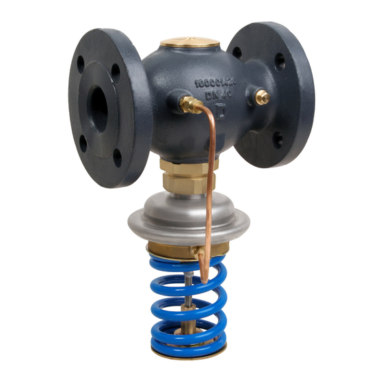
AVA – PN 25 / DN 15 - 50
DN 15 - 50
∆p = 1.0 - 4.5
ENgLIsh
DANsK
DEUTsCh
EsPAÑOL
NEDERLANDs
sLOVENŠČINA
POLsKI
LIETUVIų K.
РУССКИЙ
ROMÂNĂ
73695080 DH-SMT/SI
DN 15 - 50
∆p = 3 - 11
Pressure relief controller AVA
Trykaflastningsregulator AVA
Überströmregler AVA
Reguladores de presión de alivio AVA
Overstort drukregelaar AVA
Prelivni regulator nadtlaka AVA
Regulator upustowy ciśnienia AVA
Slėgio reguliatorius „prieš save" AVA
Регулятор давления «до себя» AVA
Regulator de reducere a presiunii AVA
VI.DB.W2.8L
DN 32 - 50
∆p = 1.0 - 4.5
© Danfoss 04/2009
DN 32 - 50
∆p = 3 - 11
www.danfoss.com
www.danfoss.dk
www.danfoss.de
www.danfoss.es
www.danfoss.nl
www.danfoss.si
www.danfoss.pl
www.danfoss.cz
www.danfoss.ru
www.incalzire.danfoss.com
Page 5
Side 6
Seite 7
Página 8
Blz. 9
Stran 10
Strona 11
Puslapis 12
Стр. 13
Pagina 14
1
Advertisement

Related Manuals for Danfoss AVA


Summary of Contents for Danfoss AVA
- Page 1 Instructions AVA – PN 25 / DN 15 - 50 DN 15 - 50 DN 15 - 50 DN 32 - 50 DN 32 - 50 ∆p = 1.0 - 4.5 ∆p = 3 - 11 ∆p = 1.0 - 4.5 ∆p = 3 - 11...
- Page 2 11/4 L1 2) Δp = 1.0 - 4.5 Δp = 3 - 11 H1 Δp = 1.0 - 4.5 H1 Δp = 3 - 11 Note: other flange dimensions - see table for tailpieces VI.DB.W2.8L 73695080 DH-SMT/SI © Danfoss 04/2009...
- Page 3 ❶ ❷ < 100 °C > 100 °C ❸ ② ① ③ L (mm) ④ ⑤ ⑥ ⑦ ⑧ ❹ > 100 °C < 100 °C ① VI.DB.W2.8L 73695080 DH-SMT/SI © Danfoss 04/2009...
- Page 4 ❻ ⑤ ④ ③ ① ② ❼ ❽ ① Δp = 1.0 - 4.5 bar ② ① ④ ③ 17 mm VI.DB.W2.8L 73695080 DH-SMT/SI © Danfoss 04/2009...
- Page 5 ②. Installation Location and 3. Slowly open shut-off devices in the Installation scheme ❷ supply pipeline ③. AVA by-pass mounting Leak and Pressure Tests Valve Installation ❸ To avoid inadmissible pressures on the 1. Clean pipeline system prior to assembly.
- Page 6 • Drejes til højre ③ øges sætpunktet (fjederen spændes). Indbygning ❷ • Drejes til venstre ④ reduceres sætpunktet (fjederen udløses). AVA by-pass-montering Ventilen lukkes uden tryk. Ventilen åbnes, når trykket foran ventilen ① kommer over Plombering ❽ det justerede sætpunkt. Sætpunktsstilleskruen kan om nødvendigt forsegles med en plombe ①.
- Page 7 • Rechtsdrehung ③ erhöht den Sollwert Einbauort, Einbauschema ❷ (Feder spannen). Inbetriebnahme ❻ • Linksdrehung ④ reduziert den AVA Einbau im Bypass Sollwert (Feder entspannen). Plombierung ❽ Ohne Druck bleibt das Ventil geschlossen. Das Ventil öffnet sich, wenn der Druck Bei Bedarf kann der Sollwertsteller ①...
-
Page 8: Montaje
❷ • Girando a la izquierda ④ reduces el punto de ajuste (relajando el muelle). AVA Montaje en bypass La válvula está cerrada si no hay presión. La válvula abre cuando la presión delante sellado ❽ de la válvula ① sobrepasa el valor ajustado. -
Page 9: Montage
Plaats in de installatie en Kijk naar de de drukmeters ②. installatieschema ➋ • Rechtsom draaien ③ verhoogt de AVA pass montage instelling (de veer wordt gespannen). Zonder druk is de afsluiter gesloten. • Linksom draaien ④ verlaagt de De regelaar opent als de druk voor de instelling (de veer wordt ontspannen). - Page 10 Lokacija namestitve in shema nastavitveno točko tlaka (napenjate vgradnje ❷ vzmet). • Vrtenje v levo ④ znižuje nastavitveno AVA vgradnja v by-pass Ventil je brez tlaka zaprt. Ventil odpira točko (sprostite vzmet). kadar nadtlak pred ventilom ① naraste nad nastavljeno vrednost. Plombiranje ❽...
- Page 11 ①. For flange dimensions - see table for tailpieces. Tok postępowania: Miejsce i schemat montażu ➋ 1. Uruchomić układ zgodnie z AVA montaż na obejściu „Napełnienie układu, pierwsze Uruchomienie ❻ uruchomienie”. Otworzyć całkowicie wszelką armaturę odcinającą w układzie regulowanym.
- Page 12 • Pasukus į dešinę ③ nustatymo vertė Montavimo vieta ir montavimo didėja (įtempiama spyruoklė). schema ➋ • TPasukus į kairę, ④ nustatymo vertė mažėja (atleidžiama spyruoklė). AVA montavimas apvade Be slėgio vožtuvas yra uždarytas. Vožtuvas atsidaro, kai slėgis ① pakyla aukščiau Plombavimas ❽ nustatytos vertės. Vertės nustatymo rankeną galima užplombuoti specialiu laidu ①, jeigu tai...
-
Page 13: Область Применения
Размещение регулятора и схема стрелки ④ снижает значение давления Клапан закрыт при отсутствии давления. установки ➋ (ослабляет пружину). Клапан открывается при увеличении AVA установка на байпасе давления до него ① выше установленного значения. Пломбирование ❽ Монтаж клапана ❸ При необходимости устройство... - Page 14 Poziţie de instalare şi schemă de Observaţi manometrul ②. instalare ❷ • Rotirea spre dreapta (în sensul acelor Umplerea sistemului, prima pornire Montare AVA în by-pass de ceasornic) ③ creşte valoarea de Pentru a evita diferenţele prea mari de referinţă (comprimă arcul). presiune de pe regulator, respectaţi • Rotirea spre stânga (în sens invers Instalare vană...
- Page 15 VI.DB.W2.8L 73695080 DH-SMT/SI © Danfoss 04/2009...
- Page 16 VI.DB.W2.8L 73695080 DH-SMT/SI © Danfoss 04/2009...
Need help?
Do you have a question about the AVA and is the answer not in the manual?
Questions and answers