
Related Manuals for Kubota LA463


Summary of Contents for Kubota LA463
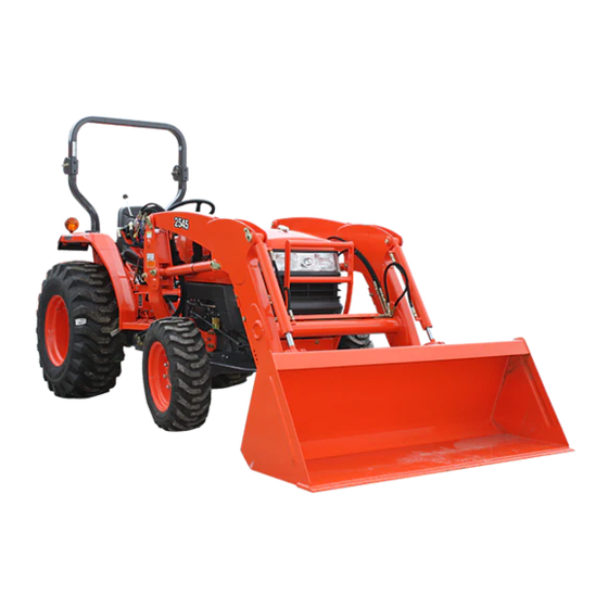
- Page 1 OPERATOR'S MANUAL MODEL LA463 AW . G . 10 - 10 . - . AK Code No. 7J244-6912-1 READ AND SAVE THIS MANUAL - Original instructions - PRINTED IN U.S.A. © KUBOTA Corporation 2003...
- Page 2 Definitions KUBOTA Corporation is ··· Two Wheel Drive Four Wheel Drive Since its inception in 1890, KUBOTA Corporation has grown to American Petroleum Institute rank as one of the major firms in Japan. ASABE American Society of Agricultural and Biological Engineers, USA...
- Page 3 FOREWORD You are now the proud owner of a KUBOTA Loader. This loader is a product of KUBOTA quality engineering and manufacturing. It is made of fine materials and under a rigid quality control system. It will give you long, satisfactory service. To obtain the best use of your loader, please read this manual carefully.
-
Page 5: Table Of Contents
CONTENTS SAFE OPERATION ....................1 SERVICING OF LOADER ................... 1 SPECIFICATIONS....................... 2 SUITABLE TRACTOR ..................... 2 LOADER SPECIFICATIONS ................... 2 BUCKET SPECIFICATIONS..................3 DIMENSIONAL SPECIFICATIONS ................. 3 OPERATIONAL SPECIFICATIONS................. 4 LOADER TERMINOLOGY..................6 PRE-OPERATION CHECK ..................7 LUBRICATION ......................7 TRANSMISSION FLUID .................. - Page 6 CONTENTS REMOVING THE LOADER ..................24 STORING THE LOADER ..................26 REINSTALLING THE LOADER................. 27...
- Page 7 ISO 24410, first edition 2005-04-15. 3. For your safety, a ROPS with a seat belt is strongly A Use of a non-Kubota attachment that does not comply recommended by KUBOTA in almost all applications. with ISO 24410 or the improper positioning of...
- Page 8 SAFE OPERATION 21. Allow for the loader length when making turns. 2. OPERATING THE LOADER 3. AFTER OPERATING THE LOADER 1. Operate the loader only when properly seated at the controls. Do not operate from the ground. 1. When loader work is complete and parking or storing, 2.
- Page 9 SAFE OPERATION DANGER,WARNING AND CAUTION LABELS...
- Page 10 SAFE OPERATION...
- Page 11 2. Clean danger, warning and caution labels with soap and water, dry with a soft cloth. 3. Replace damaged or missing danger, warning and caution labels with new labels from your local KUBOTA dealer. 4. If a component with danger, warning and caution label (s) affixed is replaced with new part, make sure new label (s) is (are) attached in the same location (s) as the replaced component.
-
Page 13: Safe Operation
However, when in need of parts or major service, be sure to see your KUBOTA dealer. For service, contact the KUBOTA dealership from which you purchased your loader or your local KUBOTA dealer. When in need of parts, be prepared to give your dealer the loader serial number. -
Page 14: Specifications
SPECIFICATIONS SPECIFICATIONS SUITABLE TRACTOR LA463: L2800, L3400, L3700SU LOADER SPECIFICATIONS LOADER MODEL LA463 TRACTOR MODEL L2800, L3400, L3700SU WHEEL BASE(WB) mm (in) 1610 (63.4) FRONT TIRES 7-16 REAR TIRES 11.2-24 BORE mm (in) 45 (1.77) BOOM CYLINDER STROKE mm (in) 476 (18.7) -
Page 15: Bucket Specifications
SPECIFICATIONS BUCKET SPECIFICATIONS LOADER MODEL LA463 MODEL SQUARE 60" TYPE RIGID WIDTH mm (in.) 1525 (60) DEPTH (L) mm (in.) 509 (20) HEIGHT (M) mm (in.) 562 (22.1) LENGTH (N) mm (in.) 591 (23.3) STRUCK m (CU.FT.) 0.23 (8.1) CAPACITY HEAPED m (CU.FT.) -
Page 16: Operational Specifications
SPECIFICATIONS OPERATIONAL SPECIFICATIONS LOADER MODEL LA463 TRACTOR MODEL L2800, L3400, L3700SU LIFT CAPACITY (BUCKET BOTTOM MID POINT) kg (lbs.) 460 (1014) LIFT CAPACITY (BUCKET PIVOT PIN, MAX. HEIGHT) kg (lbs.) 518 (1142) LIFT CAPACITY (500mm FORWARD, MAX. HEIGHT) kg (lbs.) - Page 17 SPECIFICATIONS LA463...
-
Page 18: Loader Terminology
SPECIFICATIONS LOADER TERMINOLOGY (1) Hydraulic control valve (6) Boom (2) Side frame (7) Bucket cylinder (3) Mounting pin (8) Bucket (4) Main frame (5) Boom cylinder... -
Page 19: Pre-Operation Check
PRE-OPERATION CHECK PRE-OPERATION CHECK LUBRICATION TRANSMISSION FLUID Lubricate all grease fittings with SAE multipurpose Check the tractor transmission fluid level. Add fluid if grease. necessary. Refer to the tractor operator's manual for instructions and proper fluid. Repeat this check after purging air from the system. -
Page 20: Rear Ballast
PRE-OPERATION CHECK REAR BALLAST To avoid personal injury: A For tractor stability and operator's safety, rear ballast should be added to the rear of the tractor in the form of 3-point counter weight and rear wheel ballast. The amount of rear ballast will depend on the application. -
Page 21: Tire Inflation
PRE-OPERATION CHECK TIRE INFLATION TEST OPERATION Ensure that the tractor tires are properly inflated. Refer to the tractor operator's manual for optional tires. To avoid serious personal injury: BInflation pressure A Keep engine speed at low idle during the test operation. -
Page 22: Position Bucket Control Valve Type
PRE-OPERATION CHECK REMOVING AIR FROM THE HYDRAULIC B4 Position bucket control valve type SYSTEM Repeat raising and lowering the boom and bucket operations until all the air is removed from the system and the system responds properly. A Do not move the control lever into the float position when the bucket is off the ground. -
Page 23: Operating The Loader
OPERATING THE LOADER OPERATING THE LOADER FILLING THE BUCKET The loader should be operated with the tractor engine speed depending on the application and the operator's Approach and enter the pile with a level bucket. level of experience. Excessive speeds are dangerous, and may cause bucket spillage and unnecessary strain on the tractor and loader. -
Page 24: Lifting The Load
OPERATING THE LOADER LIFTING THE LOAD CARRYING THE LOAD When lifting the load, keep the bucket positioned to avoid Position the bucket just below the level of the tractor hood spillage. for maximum stability and visibility, whether the bucket is loaded or empty. -
Page 25: Dumping The Bucket
OPERATING THE LOADER DUMPING THE BUCKET OPERATING WITH FLOAT CONTROL Lift the bucket just high enough to clear the side of the During operation on hard surfaces, keep the bucket level vehicle. Move the tractor in as close to the side of the and put the lift control in the float position to permit the vehicle as possible, then dump the bucket. -
Page 26: Loading From A Bank
OPERATING THE LOADER LOADING FROM A BANK It is important to keep the bucket level when approaching a bank or pile. This will help avoid gouging the work area. Choose a forward gear that provides a safe ground speed and power for loading. To avoid serious personal injury: A Be extra careful when working on inclines. -
Page 27: Peeling And Scraping
OPERATING THE LOADER PEELING AND SCRAPING LOADING LOW TRUCKS OR SPREADERS FROM A PILE Use a slight bucket down angle, travel forward, and hold the lift control forward to start the cut. Make a short cut For faster loading, minimize the angle of turn and length and break-out cleanly. -
Page 28: Backfilling
OPERATING THE LOADER BACKFILLING Leave dirt which drifts over the side of the bucket for final cleanup. Approach the pile with the bucket flat. Pile dirt on the high side for easier backfilling on a slope. Poor operating methods will move less dirt and make it more difficult to hold a level grade. -
Page 29: Handling Large Heavy Objects
OPERATING THE LOADER HANDLING LARGE HEAVY OBJECTS VALVE LOCK To avoid injury from crushing: To avoid serious personal injury or death: A Do not utilize the valve lock for machine A Handling large, heavy objects maintenance or repair. dangerous due to : A The valve lock is to prevent accidental (A)Danger of rolling the tractor over. -
Page 30: Attaching Attachments
This quick attach coupler allows the operator to change easily without the use of tools. To avoid serious personal injury or death: A Use of a non-Kubota attachment that does not comply with ISO 24410 or the improper positioning of handle(s) or non-protrusion of... - Page 31 OPERATING THE LOADER 6. Visually verify when pushing the quick attach coupler handles into locked position that the latch pins rotate completely and are located underneath the stop of the To avoid serious personal injury or death: quick attach coupler. A The following engagement points are critical.
-
Page 32: Detaching Attachments
OPERATING THE LOADER DETACHING ATTACHMENTS MAINTENANCE 1. Detaching attachments is done in the reverse of 1. Attachments are secured to the quick attach coupler attaching attachments. The procedure is below. with an over center latching system. It is important that 2. -
Page 33: Maintenance
MAINTENANCE MAINTENANCE LUBRICATION 1. Lubricate all grease fittings every 10 hours of To avoid personal injury: operation. Also, lubricate joints of control lever linkage A Be sure to check and service the tractor on a every 10 hours. High quality grease designating flat place with the bucket on the ground, engine "extreme pressure"... -
Page 34: Re-Tightening Of Hardware
MAINTENANCE RE-TIGHTENING OF HARDWARE DAILY CHECKS After 20 to 30 hours of initial loader operation, re-tighten 1. Check all hardware daily before operation. Tighten hardware to torque values as specified in the all mounting bolts and nuts to the required torque value as "Installation Instructions"... -
Page 35: General Torque Specification
MAINTENANCE BGeneral torque specification American standard screws, bolts and nuts with UNC or Metric cap screws UNF threads SAE grade No. SAE GR.5 SAE GR.8 property class 8.8 Approx. SAE GR 5 (N-m) 11.7 to 15.8 16.3 to 19.8 (N-m) 9.8 to 11.2 (kgf-m) 1.19 to 1.61... - Page 36 REMOVING THE LOADER REMOVING THE LOADER To avoid personal injury: A Make sure an approved bucket is attached before removing the loader from the tractor. A For removing the loader, choose flat and hard ground, preferably concrete. A If the ground surface is soft, place suitable planks on the ground for the bucket and stands.
- Page 37 REMOVING THE LOADER (1) Protective plug 15. Start the engine and slowly back the tractor away from the loader.
- Page 38 STORING THE LOADER STORING THE LOADER 1. Store the loader in a clean dry place. 2. Make sure the loader is properly supported. 3. Attach the protective plugs and caps to the couplers to protect them from dust. 4. Check all hydraulic hoses and connections. Repair or replace them if necessary.
- Page 39 REINSTALLING THE LOADER REINSTALLING THE LOADER A Adjust the route of the hoses as shown. To avoid personal injury: A When starting the engine and operating the control valve, always sit in the operator's seat. 1. Slowly drive the tractor between the loader side frames until the rear portion of both side frames touches the main frames as shown.
- Page 40 REINSTALLING THE LOADER 10. Store the stands to their original positions and secure them with the spring pins as shown. (1) Stand (2) Spring pin 11. Start the engine. 12. Lower the boom and level the bucket.
Need help?
Do you have a question about the LA463 and is the answer not in the manual?
Questions and answers