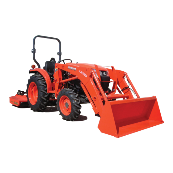
Summary of Contents for Kubota LA525
- Page 1 ASSEMBLY INSTRUCTIONS MODEL LA525 1AIABEFAP0280 READ AND UNDERSTAND THIS MANUAL BEFORE ASSEMBLING © PRINTED IN U.S.A. KUBOTA Corporation 2013 Code No. 7J294-6915-3 English (U.S.A.) AX. L. 3-3 . -. K...
-
Page 2: Table Of Contents
CONTENTS ASSEMBLY INSTRUCTIONS ..................1 TO THE DEALER..................... 1 SAFETY ........................1 UNPACKING AND CHECKING PARTS ..............2 Unpacking Wooden Crate....................2 Checking Parts .........................3 TRACTOR PREPARATION ..................4 BEFORE ASSEMBLY ....................4 ASSEMBLING LOADER KIT ................... 5 Boom Assembly........................ 5 Main Frame........................ -
Page 3: Assembly Instructions
ASSEMBLY INSTRUCTIONS ASSEMBLY INSTRUCTIONS TO THE DEALER (3) Working clothes which may 1. This manual contains procedures intended to assist be pinched or caught in the the dealer in unpacking and assembling the product equipment must not be worn. before delivering to the customer. Loose clothing can cause The customer's purchase is based on confidence in serious injury or death. -
Page 4: Unpacking And Checking Parts
ASSEMBLY INSTRUCTIONS UNPACKING AND CHECKING PARTS 3. After assembly check (1) Before operating or test driving the equipment, read and understand the operator's manual. BUnpacking Wooden Crate (2) Once the equipment is fully 1. Cutting metal bands (if two are banded together). assembled, select a safe Metal bands hold the two crates together as one. -
Page 5: Checking Parts
(1) Bucket (2) Boom assembly (3) Main frame LH (4) Main frame RH (5) Front guard (6) Control valve assembly (7) Hydraulic block (8) Parts box (9) Level indicator (Option) (10) Quick attach coupler (LA525FL : Option / LA525 : Standard) -
Page 6: Tractor Preparation
ASSEMBLY INSTRUCTIONS TRACTOR PREPARATION A When using the tapered adapters, wrap the seal tape around the thread part 2 or 3 times. At this time, 1. Remove the mid mount mower from the tractor if ensure all contaminates are removed from the equipped. -
Page 7: Assembling Loader Kit
2-M6 x 55 bolts 2-M6 locking nuts (2) 2-Pin 3 (25.4 mm (1.0 in.) dia.) (Black) 2-M6 x 55 bolts 2-M6 locking nuts [LA525] Quick Hitch (1) Side frame (5) 2-M6 locking nuts (2) Boom (6) 2-pins (25.4 mm (3) 2-pins (25.4 mm (1.0 in.) dia.) -
Page 8: Main Frame
ASSEMBLY INSTRUCTIONS 3. Raise the boom until the stands can be rotated. [LA525] Quick Hitch (1) 2-Labels, danger (A) 50 mm (1.97 in.) (1) Belt sling (Part No. 7J802-3648-5) (B) 10 mm (0.39 in.) (2) Boom 4. Remove the spring pins holding the stands to the boom. -
Page 9: Hydraulic Line
ASSEMBLY INSTRUCTIONS 4. Connect the hose from pump port on the control valve assembly to pump port on the hydraulic block. BHydraulic Line 5. Connect the hose from tank port on the control valve assembly to tank port on the hydraulic block. 1. -
Page 10: Front Guard
ASSEMBLY INSTRUCTIONS 3. Assemble the specified parts as shown in the following figure. BFront Guard 1. Attach the front guard and front bumper together to the front axle frame, using the four bolts (2) in the kit. (1) 2-M20 x 80 hex. bolts (2) 4-M20 plain washers (large) (3) 4-M20 plate springs (1) Front guard... - Page 11 ASSEMBLY INSTRUCTIONS 4. Assemble the specified parts as shown in the following A Before moving the tractor or the front loader, make figure. sure the front guards are tightly locked. (1) 4-M20 hex. nuts (A) 12 to 13 mm (1) Front guard lever (A) "Lock position"...
-
Page 12: Level Indicator (Option)
ASSEMBLY INSTRUCTIONS 3. Attach the level indicator. BLevel Indicator (Option) 1. Remove two original pins from the boom (RH). A Make sure the indicator assy. is attached in its specified direction, as shown below. (1) Original pin (1) Indicator assy. (2) PIN 8 2. -
Page 13: Pre-Operation Check
ASSEMBLY INSTRUCTIONS PRE-OPERATION CHECK [HST Type] BLubrication Lubricate all grease fittings with grease. High quality grease designating "extreme pressure" and containing Molybdenum disulfide is recommended. This grease may specify "Moly EP" on its label. (1) Dipstick (A) Oil level is acceptable within this range BTransmission Fluid Check the tractor transmission fluid level. -
Page 14: Estimated Assembly Time
Assembly times on the table are just reference under the average conditions with following assumption. 1. Assembly by one worker. 2. Following tools and equipment are prepared. (1) Chain hoist or crane. (2) Impact wrench, Ratchet wrench, Torque wrench, Socket wrench, Spanner wrench. (3) Nylon strap. LA525 1.5 hour... -
Page 15: Tightening Torque Of Bolts And Nuts
ASSEMBLY INSTRUCTIONS TIGHTENING TORQUE OF BOLTS AND NUTS If the torque levels are specified in the text, follow that specification. American standard screws, bolts and nuts with UNC or Metric cap screws UNF threads SAE grade No. SAE GR.5 SAE GR.8 property class 8.8 Approx.


Need help?
Do you have a question about the LA525 and is the answer not in the manual?
Questions and answers