Table of Contents
Advertisement
Available languages
Available languages
Quick Links
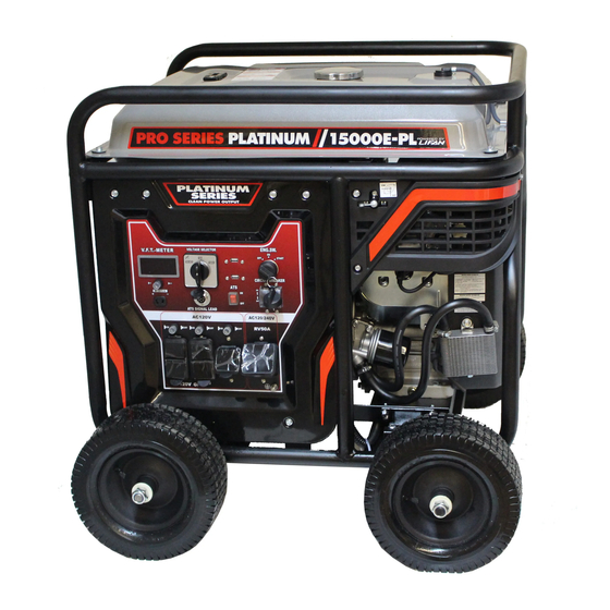
Model LF-15000E-PL
Model LF-15000E-PL
Please read this manual carefully before operating your new portable generator.
(CA) in the model number designated California Compliant by CARB 7/2020
Unit designed for
Unit designed for
Home Standby
Home Standby
Power
Power
SEE INFORMATION INSIDE
SEE IN
FORMATION INSIDE
ALL PRODUCT, PROD-
UCT SPECIFICATIONS
AND DATA ARE SUB-
JECT TO CHANGE
WITHOUT NOTICE TO
IMPROVE RELIABILITY,
FUNCTION OR DESIGN
OR OTHERWISE.
Advertisement
Table of Contents

Related Manuals for LIFAN Power USA Platinum Series


Summary of Contents for LIFAN Power USA Platinum Series
- Page 1 Unit designed for Unit designed for Home Standby Home Standby Power Power SEE IN SEE INFORMATION INSIDE FORMATION INSIDE ALL PRODUCT, PROD- UCT SPECIFICATIONS AND DATA ARE SUB- JECT TO CHANGE WITHOUT NOTICE TO Model LF-15000E-PL Model LF-15000E-PL IMPROVE RELIABILITY, FUNCTION OR DESIGN OR OTHERWISE.
- Page 2 OPERATING INSTRUCTIONS AND OWNER’S MANUAL LF-15000E-PL PLEASE KEEP AND READ THIS MANUAL CAREFULLY BEFORE OPERATING YOUR NEW LIFAN POWER USA PORTABLE GENERATOR STANDBY POWER CAPABILITY Your Pro Series Platinum 15000E-PL generator is equipped and designed to connect and communicate with the 100 amp Automat- ic Transfer Switch, which is sold separately, to be used as a Home Standby Power System during any power outage or threatened power outage.
- Page 4 SPECIAL HAZARDS • CO Poisoning: Exhaust from engine contains carbon monoxide, a poisonous gas that can cause carbon monoxide poisoning and possible death if inhaled. • Electric shock: Operating equipment in wet conditions or near water can cause electric shock. •...
-
Page 5: Table Of Contents
TABLE OF CONTENTS Preface Operation of Generator ... . . Product Specifications ... Storing the Unit ....Safety Instructions . -
Page 6: Preface
PREFACE Thank you for choosing LIFAN Power USA for your Power Equipment needs. LIFAN Pow- er USA prides itself on providing quality products at affordable pricing, creating the “Best Equipment Value on Today’s Market!” Your Portable Generator utilizes our Industrial Grade Gasoline Engines and is intended for OUTDOOR USE ONLY. -
Page 7: Product Specifications
PRODUCT SPECIFICATIONS LF15000E-PL 120V / 240V Voltage 15000 watts AC Surge Output 14000 watts Rated AC Output 120 amps Maximum AC Amperage 60hz AC Cycle Battery Maintainer Storage Capacitors 1 ea. 12V 8.3amp DC Receptacle 2 Duplex 120V 20amp AC GFCI Receptacle 1 ea. - Page 9 ONLY operate generators outdoors. Exhaust gas must be prevented from entering confined areas. Direct exhaust gas away from windows, doors, ventilation, and other openings. Do not operate this gen- erator inside or under any buildings. WHEN ADDING OR DRAINING FUEL •...
- Page 10 CAUTION! Improper use and care of this generator will cause damage and shorten its lifespan. Failure to follow these actions will void all warranties. • Use generator only for appropriate and designated purposes. • The dealer or customer helpline (1-866-471-7464) can instruct you on intended uses.
-
Page 11: Controls And Features
CONTROLS AND FEATURES LF-15000E-PL 1 Generator 4 Engine 2 Steel frame 5 Generator cover 3 Control panel 6 Muffler end cover... - Page 12 CONTROLS AND FEATURES LF-15000E-PL Generators supply voltage and amperage as sine-wave-shaped energy. As devices are connected to the generator, the sine-wave shaped energy is disrupted. Measurement of this disruption is known as total harmonic distortion. total harmonic distortion. The lesser the percentage of total harmonic distortion, the greater the generator’s ability to smoothly power a load.
- Page 13 LEGEND Fuel Level Sensor - Displays current fuel level Fuel Tank Cap - Vented fuel cap must be properly installed at all times during operation Receptacle Panel - see product specifications for individual model Double Pole Circuit Breaker (AC) - protects receptacles & generator from overload Crankcase Oil Dipstick / Oil Fill Hole Cap - check/fill engine oil On / Off Switch - set to “ON”...
-
Page 14: Pre-Operating Instructions
PRE-OPERATING INSTRUCTIONS WHEEL KIT ASSEMBLY FOR LF-15000E-PL Wheel Kit Installation Directions: NOTE: Install Wheel Kit BEFORE Filling the Generator with Fuel or Oil. Never Tip a Unit that contains Fuel or Oil. 1. Tip Generator so Engine End is up. 2. - Page 15 PRE-OPERATING INSTRUCTIONS BATTERY SPECIFICATIONS Your generator is equipped with the latest battery technology: the lith- ium ion battery. Lightweight, yet with advanced cold cranking amper- age available to start your engine with the ease. Long life expectancy and faster recharging. See the battery specifications below for com- plete details.
-
Page 16: Engine Fuel Level Check
PRE-OPERATING INSTRUCTIONS: SETUP WHEN ADDING FUEL • Turn generator off and let it cool for a minimum of three minutes before removing fuel cap. • Turn and remove cap slowly in order to relieve residual tank pressure. • Always fill the fuel tank with the unit outdoors. •... -
Page 17: Engine Oil Level Check
PRE-OPERATING INSTRUCTIONS: SETUP CAUTION: Any attempt to start the generator before it has been properly serviced may result in engine failure and void warranty. ADD ENGINE OIL: Refer to the diagram below. 1. Place generator on level surface. 2. Clean area around Oil Hole Dipstick/Plug & Unscrew Oil Hole Dipstick/Plug. - Page 18 PRE-OPERATING INSTRUCTIONS: SETUP WHEN ADDING FUEL • Turn generator off and let it cool for a minimum of three minutes before removing fuel cap. • Turn and remove cap slowly in order to relieve residual tank pressure. • Always fill the fuel tank with the unit outdoors. •...
-
Page 19: Operation Of Generator
OPERATING YOUR GENERATOR CHECK AIR CLEANER ELEMENT: Refer to “Air Cleaner Maintenance” in the Maintenance section of this Owner’s Manual to ensure Air Cleaner Element is in operable condition. - Page 20 OPERATING YOUR GENERATOR CONNECTING ELECTRICAL LOADS: 1. Ensure engine is started before plugging in any electrical appliance. 2. Plug in desired 120 Volt loads to the 120 Volt U-Ground and 240 Volt loads to the 240 Volt receptacles. Always plug appliances into the generator with appliance in its “OFF” position. 3.
- Page 21 OPERATING YOUR GENERATOR 1. Unplug all electrical loads from the lever to the engaged position per the generator. instruction label on the generator main frame. 2. Make sure the generator is in a level 5. Place the On/Off switch in the “ON” (l) position.
- Page 22 OPERATING YOUR GENERATOR LOW OIL ALARM SYSTEM: This model is equipped with a Low Oil Alert System designed to avoid engine damage from insufficient oil in the crankcase. The Low Oil Alarm System will stop the engine automatically before the oil level in the crankcase drops below safe operating levels. STOPPING THE GENERATOR: Refer to Controls and Features section for diagram.
- Page 23 OPERATING YOUR GENERATOR USAGE IN HIGH ALTITUDE REGIONS: In regions with high altitude, the standard carburetor produces overly dense combinations of fuel and air, which result in decreased engine performance and increased fuel consumption. To maintain high engine performance at high altitudes, install a high altitude carburetor main spray nozzle and re-adjust the adjusting screw for idle speed.
- Page 24 • To prevent electrical shock from faulty appliances, the generator should be grounded. Connect a length of heavy cable between the generator’s grounding terminal and an external ground source. • Indoor use of a generator can kill quickly. Generators should be used outdoors only.
- Page 25 • Only operate generator outdoors. • Prevent exhaust gas from entering, through windows doors or ventilation intakes, any confined areas. • DO NOT operate generator inside any enclosed or roofed areas. This includes the generator compartment of any recreational vehicle (RV). •...
-
Page 26: Storing The Unit
STORING THE UNIT STORAGE Before long term storage of your power equipment product, typically 30 days or more, perform the following: 1. Set the fuel valve to the “OFF” position. 2. Let the unit continue to run until it stops itself, burning all of the fuel in the fuel system. 3. -
Page 27: Maintenance
MAINTENANCE NOTE: Refer to Following Procedures for Proper Method to Perform Maintenance MAINTENANCE SCHEDULE PROCEDURE TIME Engine Oil Check Each Use After Each 40 Hours of use (for initial Replace Engine Oil break-in - after first 10 hours of use) Air Cleaner Filter Check Each Use When Needed or After Every 50 Hours... - Page 28 MAINTENANCE NOTE: Refer to Following Procedures for Proper Method to Perform Maintenance OIL CHANGE PROCEDURES: Refer to Controls and Feature section for diagram. Periodic Maintenance of your engine oil should be performed after each 40 hours of use of you Power Equipment Product.
- Page 29 MAINTENANCE PROPER MAINTENANCE OF THE UNIT WILL INCREASE THE LIFE OF YOUR PRODUCT. THE OIL MUST BE CHANGED ON A REGULAR BASIS FOR PROPER OPERATION, AND RELIABILITY AND TO ALSO MAINTAIN THE WARRANTY ON THIS PRODUCT. AIR CLEANER MAINTENANCE: 1. Remove the clip or the wing nut to remove and check the air filter element.
- Page 30 MAINTENANCE SPARK PLUG MAINTENANCE 1. Remove Spark Plug Cap (refer to “Spark Plug Cap Removal” figure below.) 2. Remove Spark Plug with socket and handle supplied with your unit (refer to “Spark Plug Removal” figure below.) 3. Clean any carbon build-up around the Spark Plug. 4.
-
Page 31: Troubleshooting
MAINTENANCE 4. Fit a new rubber washer into place and re-attach fuel bowl to Fuel Filter Fuel Filter the carburetor, and either clean Element Removal Element Assembly or replace the fuel filter element. Re-assemble the fuel filter element. TROUBLESHOOTING IF THE ENGINE WILL NOT START: 1. -
Page 32: Safety
GENERATOR SAFETY 1. Never operate gasoline engine powered products in any enclosed spaces, as they produce deadly Carbon Monoxide Poisonous Gases. 2. Never hook a generator directly to your home circuit without the proper installation by a Licensed Electrician and without the proper power transfer devices. 3. -
Page 33: Wattage Chart
WATTAGE CHART... - Page 34 WATTAGE CHART...
- Page 35 WATTAGE CHART RECORD PURCHASE HERE MODEL # _____________________________________________________ ENGINE ID # _________________________________________________ DATE OF PURCHASE _________________________________________ PURCHASE LOCATION _______________________________________ -CA INDICATES THIS UNIT IS CARB CERTIFIED...
- Page 36 CONVERTING AMPS OR HORSEPOWER INTO WATTS If necessary, use these formulas: Watts = Amps x Volts Running Watts* = Horsepower x 932** (for motors) Remember, this worksheet lists average power requirements a particular manufacturer’s device may use more or less than the listed wattage. •...
-
Page 37: Limited Warranty Policy
LIMITED WARRANTY POLICY This warranty is limited to the following Lifan Power and Storm Series products that are distributed by the EquipSource LLC, d/b/a LIFAN POWER USA, located at 2205 Industrial Park Road, Van Buren, AR 72956. Effective date is 1/1/2019. LENGTH OF WARRANTY Residential Use** Commercial/Rental**... - Page 38 LIMITED WARRANTY POLICY This warranty is not valid for products or parts affected or damaged by accident, collision, normal wear, fuel contamination, abuse, neglect, misuse, alteration and/or unsuitable use or unauthorized parts replacement. Mower decks and blades are specifically not warranted for impact or abrasive damage. Warranty becomes void if the customer fails to install, maintain, and/or operate the product in accordance with the instructions and recommended actions of Lifan set forth in the owner’s manual.
- Page 39 LIMITED WARRANTY POLICY DISCLAIMER OF IMPLIED WARRANTIES This limited warranty is in lieu of all other expressed or implied warranties, including any warranty of the unit’s fitness for any particular use and any implied warranty of MERCHANTABILITY otherwise applicable to Lifan Power Equipment and its affiliated companies shall not be liable for any special, incidental or consequential damage, including lost profits.
-
Page 40: Wiring Diagram
LF-15000E-PL WIRING DIAGRAM... - Page 42 PELIGROS ESPECIALES • Envenenamiento por CO: El escape del motor contiene monóxido de carbono, un gas venenoso que puede causar intoxicación por monóxido de carbono y una posible muerte si se inhala. • Descarga eléctrica: El funcionamiento del equipo en condiciones de humedad o cerca del agua puede provocar una descarga eléctrica.
- Page 43 PREFACIO Gracias por elegir LIFAN Power USA para sus necesidades de equipos eléctricos. LI- FAN Power USA se enorgullece de ofrecer productos de calidad a precios asequibles, creando el “Mejor valor de equipo en el mercado actual”. Su generador portátil utiliza nuestros motores de gasolina de grado industrial y está diseñado para USO EN EXTERIORES SOLAMENTE.
- Page 44 Usar un generador en el interior puede MATAR En utilisant un générateur à l'intérieur peut vous tuer en EN MINUTOS! quelques minutes! Escape del generador contiene monóxido de carbono. D'air du générateur contient du monoxyde de carbone. Este es un veneno que no se puede ver ni oler. C'est un poison qui vous ne pouvez pas voir ou sentir.
- Page 45 SOLO opere genera- dores en exteriores. Debe evitarse que los gases de escape entren en áreas confinadas. Dirija los gases de es- cape lejos de ventanas, puertas, ventilación y otras aberturas. No opere este generador dentro o debajo de edifi- cios.
- Page 46 ¡PRECAUCIÓN! El uso y cuidado inadecuado de este generador provocará daños y acortará su vida útil. El incumplimiento de estas acciones anulará todas las garantías. • Utilice el generador solo para los fines apropiados y designados. • El distribuidor o la línea de ayuda al cliente (1-866-471-7464) pueden instruirle sobre los usos previstos.
- Page 47 CONTROLES Y CARACTERÍSTICAS LF-15000E-PL 1 Generador 4 Motor 2 Marco de acero 5 Cubierta del generador 3 Panel de control 6 Cubierta del extremo del silenciador...
- Page 48 CONTROLES Y CARACTERÍSTICAS LF-15000E-PL Los generadores suministran voltaje y amperaje como energía en forma de onda sinusoidal. A medida que los dispositivos se conectan al generador, la energía en forma de onda sinusoidal se interrumpe. La medición de esta interrupción se conoce como distorsión armónica total. Cuanto menor sea el porcentaje de distorsión armónica total, mayor será...
- Page 49 LEYENDA Sensor de nivel de combustible: muestra el nivel de combustible actual Tapón del tanque de combustible: el tapón de combustible ventilado debe instalarse correcta- mente en todo momento durante la operación Panel de receptáculo: consulte las especificaciones del producto para el modelo individual Disyuntor bipolar (CA): protege los receptáculos y el generador contra sobrecargas Varilla medidora de aceite del cárter / Tapa del orificio de llenado de aceite: comprobar / llenar el aceite del motor...
- Page 50 PRE-OPERACIÓN INSTRUCCIONES CONJUNTO DE KIT DE RUEDAS PARA LF-15000E-PL Instrucciones de instalación del juego de ruedas: NOTA: Instale el juego de ruedas ANTES de llenar el generador con com- bustible o aceite. Nunca incline una unidad que contenga combustible o aceite.
- Page 51 PRE-OPERACIÓN INSTRUCCIONES ESPECIFICACIONES DE LA BATERIA Su generador está equipado con la última tecnología en baterías: la batería de iones de litio. Ligero, pero con un avanzado amperaje de arranque en frío disponible para arrancar el motor con facilidad. Larga esperanza de vida y recarga más rápida. Con- sulte las especificaciones de la batería a continuación para obtener detalles comple- tos.
- Page 52 INSTRUCCIONES PREVIAS A LA OPERACIÓN: CONFIGURACIÓN AL AÑADIR COMBUSTIBLE • Apague el generador y déjelo enfriar por un mínimo de tres minutos antes de quitar la tapa de combustible. • Gire y retire la tapa lentamente para aliviar la presión residual del tanque. •...
- Page 53 INSTRUCCIONES PREVIAS A LA OPERACIÓN: CONFIGURACIÓN PRECAUCIÓN: Cualquier intento de poner en marcha el generador antes de que haya recibido el servicio adecuado puede resultar en una falla del motor y anular la garantía. AGREGUE ACEITE DE MOTOR: Consulte el diagrama a continuación. 1.
- Page 54 INSTRUCCIONES PREVIAS A LA OPERACIÓN: CONFIGURACIÓN AL AÑADIR COMBUSTIBLE • Apague el generador y déjelo enfriar por un mínimo de tres minutos antes de quitar la tapa de combustible. • Gire y retire la tapa lentamente para aliviar la presión residual del tanque. •...
- Page 55 OPERANDO SU GENERADOR CONEXIÓN A TIERRA DEL GENERADOR: Consulte la sección Controles y funciones. Conecte la terminal de tierra del generador a una fuente aceptable de tierra eléctrica, como una estaca de cobre para conexión a tierra, utilizando un cable eléctrico de cobre con un diámetro mínimo de 16 calibres.
- Page 56 OPERANDO SU GENERADOR CONEXIÓN DE CARGAS ELÉCTRICAS: 1. Asegúrese de que el motor esté encendido antes de enchufar cualquier aparato eléctrico. 2. Enchufe las cargas deseadas de 120 voltios a la toma de tierra en U de 120 voltios y las cargas de 240 voltios a los receptáculos de 240 voltios.
- Page 57 OPERANDO SU GENERADOR 1. Desenchufe todas las cargas eléctricas posición de engranado según la etiqueta del generador. de instrucciones en el bastidor principal 2. Asegúrese de que el generador esté en del generador. una posición nivelada. 5. Coloque el interruptor de encendido / 3.
- Page 58 OPERANDO SU GENERADOR SISTEMA DE ALARMA DE BAJO ACEITE: Este modelo está equipado con un sistema de alerta de aceite bajo diseñado para evitar daños en el motor por falta de aceite en el cárter. El sistema de alarma de aceite bajo detendrá el motor automáticamente antes de que el nivel de aceite en el cárter caiga por debajo de los niveles de funcionamiento seguros.
- Page 59 OPERANDO SU GENERADOR USO EN REGIONES DE GRAN ALTITUD: En regiones con gran altitud, el carburador estándar produce combinaciones demasiado densas de combustible y aire, lo que resulta en un menor rendimiento del motor y un mayor consumo de combustible. Para mantener un alto rendimiento del motor a grandes altitudes, instale una boquilla de pulverización principal del carburador para grandes altitudes y reajuste el tornillo de ajuste para la velocidad de ralentí.
- Page 60 • Para evitar descargas eléctricas de aparatos defectuosos, el generador debe estar conectado a tierra. Conecte un tramo de cable pesado entre el terminal de tierra del generador y una fuente de tierra externa. • El uso de un generador en interiores puede matar rápidamente. Deben usarse generadores solo al aire libre.
- Page 61 • Solo opere el generador en exteriores. • Evite que los gases de escape ingresen, a través de las ventanas, puertas o tomas de ventilación, cualquier áreas. • NO opere el generador dentro de áreas cerradas o techadas. Esto incluye el generador compartimento de cualquier vehículo recreativo (RV).
- Page 62 ALMACENAMIENTO DE LA UNIDAD ALMACENAMIENTO Antes del almacenamiento a largo plazo de su producto de equipo de energía, general- mente 30 días o más, realice lo siguiente: 1. Coloque la válvula de combustible en la posición “APAGADO”. 2. Deje que la unidad continúe funcionando hasta que se detenga, quemando todo el combustible del sistema de combustible.
- Page 63 MANTENIMIENTO NOTA: Consulte los siguientes procedimientos para conocer el método adecuado para realizar el mantenimiento. PROGRAMA DE MANTENIMIENTO PROCEDIMIENTO EL TIEMPO Comprobación del aceite del motor Cada uso Después de cada 40 horas de uso (para Reemplace el aceite del motor el rodaje inicial, después de las prime- ras 10 horas de uso) Comprobación del filtro del...
- Page 64 MANTENIMIENTO NOTA: Consulte los siguientes procedimientos para conocer el método adecuado para realizar el mantenimiento. PROCEDIMIENTOS DE CAMBIO DE ACEITE: Consulte la sección Controles y funciones para ver el diagrama. El mantenimiento periódico de su aceite de motor debe realizarse después de cada 40 horas de uso de su producto de equipo motorizado.
- Page 65 MANTENIMIENTO EL MANTENIMIENTO ADECUADO DE LA UNIDAD AUMENTARÁ LA VIDA ÚTIL DE SU PRODUC- TO. EL ACEITE SE DEBE CAMBIAR DE FORMA REGULAR PARA EL FUNCIONAMIENTO COR- RECTO Y LA FIABILIDAD Y TAMBIÉN PARA MANTENER LA GARANTÍA DE ESTE PRODUCTO. MANTENIMIENTO DEL FILTRO DE AIRE: 1.
- Page 66 MANTENIMIENTO MANTENIMIENTO DE BUJÍAS 1. Retire la tapa de la bujía (consulte la figura “Extracción de la tapa de la bujía” a continuación). 2. Quite la bujía con el enchufe y la manija que se suministran con su unidad (consulte la figura “Extracción de la bujía” a continuación). 3.
- Page 67 MANTENIMIENTO 4. Fit a new rubber washer into place and re-attach fuel bowl to Filtro de combustible Filtro de the carburetor, and either clean Eliminación de combustible or replace the fuel filter element. elementos Ensamblaje de Re-assemble the fuel filter elementos element.
- Page 68 SEGURIDAD DEL GENERADOR 1. Nunca opere productos con motor de gasolina en espacios cerrados, ya que producen gases venenosos de monóxido de carbono letales. 2. Nunca conecte un generador directamente al circuito de su hogar sin la instalación adecuada por parte de un electricista autorizado y sin los dispositivos de transferencia de energía adecuados.
- Page 69 CONVERTIR AMPERIOS O CABALLOS DE POTENCIA EN VATIOS Si es necesario, use estas fórmulas: Watts = Amperios x Voltios Watts en funcionamiento* = Caballos de fuerza x 932** (para motores) Recuerde, esta hoja de trabajo enumera los requisitos de energía promedio que el dispositivo de un fabricante en particular puede usar más o menos que la potencia indicada.
Need help?
Do you have a question about the Platinum Series and is the answer not in the manual?
Questions and answers