Table of Contents
Advertisement
Advertisement
Table of Contents

Related Manuals for LIFAN Power USA PRO Series


Summary of Contents for LIFAN Power USA PRO Series
- Page 2 Operating Instructions Owner’sManual PRO SERIES LF4000-(CA), LF7250-(CA) LF8750iE-(CA) Record Purchase Here Model # ___________________________...
- Page 3 Engine ID # _________________________ (Unique Identifier stamped on engine crankcase) Date of Purchase ____________________ Purchase Location ____________________ PLEASE KEEP AND READ THIS MANUAL CAREFULLY BEFORE OPERATING YOURNEWPORTABLEGENERATOR (--‐CSA-CA)IndicatesthisunitisCSA (Canadian Compliant) And CARB Certified (California Compliant) (E)Indicatesthisunitis EquippedwithElectricStart PLEASE READTHE FOLLOWINGINSTRUCTIONS!
- Page 4 1. Unit Shipped with “NO OIL” in Engine or where applicable pumps and/or accessories. Check and fill with proper oil as outlined in the Owner’s Manual for the respective product. 2. For repair under Warranty or questions concerning Warranty, DO NOT return this product to the Store where purchased.
- Page 5 (LF) Indicates this unit is a LIFAN Power USAProduct (- ‐ ‐CA) Indicates this unit is CARB Certified for California (E) Indicates this unit is equipped with ElectricStart ( I ) Indicated the unit is equipped with Auto Idle Feature Table ofContents Preface Safety Instructions...
-
Page 6: Table Of Contents
Legend PRE-‐‐OPERATINGINSTRUCTIONS Assembly Battery Specifications GeneratorSetup Operation of Generator Storing the Unit Maintenance Troubleshooting Generator Wattage ReferenceWorksheet Limited Warranty Policy APPENDIX Exploded Views/Wiring Diagrams Preface Thank you for choosing LIFAN Power USA for your Power Equipment Needs.LIFANPower USA prides itself on providing quality products at affordable pricing, creatingthe“Best Equipment Value on... - Page 7 Today’s Market!” All LIFAN Power USA products are manufactured utilizing the latest technology.Builtwithqualitycomponents,yournewPowerEquipmentProductwillgiveyouyearsof dependable service. Your unit, along with all of LIFAN Power USA products a r e designed, engineered, and manufactured with LIFAN’s Industrial Grade GasolineEngine. ThisOwner’sManualwillprovideyouwithallofyourneededinformationforyournew PowerEquipmentProduct,includingSafeOperation and Maintenanceof yourunit. PleasereadthisOwner’sManualcompletelyandcarefullypriortooperation.
- Page 8 SAFETYRULES For your safety read this manual carefully.Becomefamiliar with the proper operation, care, andmaintenance of your Lifangenerator WARNING! The safety and alert symbol (A ) is used with a Rapidrecoilofstartercord(kickback) signalword(CAUTION,DANGER,WARNING),apictorialand/orsafetymess maypullhandandarmforward ageto alert you to hazards. CAUTION indicates a hazard which, towardengineatarapidrate.
- Page 9 Exhaustgasmustbepreventedfromenteringconfinedareas. Directexhaustgasawayfromwindows,doors,ventilation and ThisgeneratordoesnotmeetU.S.CoastGuardRegulation 33CFR- 183andshouldnotbeusedonmarineapplications. Donotoperategeneratorinsideorunderanybuildings. Operating Useofthisgeneratoronmarineapplicationscouldresultin injuryordeath thisgeneratorinsidethecompartmentofa recreationalvehiclewilllikelyresultindeath WARNING! TheengineexhaustfromthisgeneratorcontainschemicalsknowntothestateofCaliforniatocaus ebirthdefects,reproductiveharm,andcancer WARNING! Fuel and its vapors are extremely flammable andexplosive. Fire or explosion can cause severe burns ordeath.
- Page 10 WHEN ADDING OR DRAININGFUEL Turn generator off and let it cool for at least three minutes before removing fuel cap. Loosen cap slowly in ordertorelieve pressure in the fueltank. Fill or drain fuel tank outdoors. Do not excessively inhale fuelvapors. ...
- Page 11 WARNING! While engine is running temperature may exceed 150°F(65°C).Server burns mayoccur. Exhaust heat/gasses can ignite combustibles, structures or damage fuel tank Do NOT touch hot surfaces and do avoid exhaust gasses. causingafire. Allow generator to cool before touching. ...
- Page 12 Use generators only for appropriate and designatedpurposes. Thedealerorcustomerhelpline(1- ‐ ‐ 8 66-‐ ‐ 4 71- ‐ ‐ 7 464)caninstructyouonintendeduses. Generator must be placed on a levelsurface. Do NOT expose generator to extreme conditions. Excessive dust, moisture, and corrosive vapors will damageunit. ...
- Page 13 Generator Safety 1. Never operate gasoline engine powered products in any enclosed spaces,asthey product deadly Carbon Monoxide PoisonousGases. 2. Never hook a generator directly to your home circuit without theproper installation by a Licensed Electrician and without the proper powertransfer devices. 3.
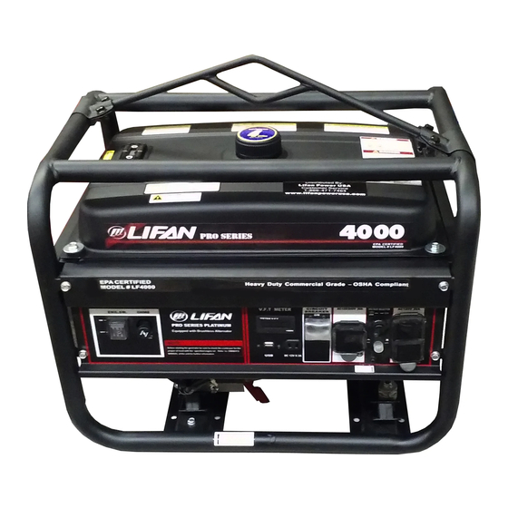
- Page 14 Products Specifications PORTABLE GENERATORS ModelSize LF4000-CA LF7250-CA LF8750iE-CA Voltage 120/240VAC&12VD 120/240VAC&12VDC 120/240VAC&12VDC ACSurgeOutput1 4000Watts 7250Watts 8750Watts RatedACOutput2 3500Watts 6500Watts 7500Watts MaximumACAmperage 28amps@120V 48amps@120V 62amps@120V ACCycle 60Hertz 60Hertz 60Hertz Brushless Altenator Storage Capacitor AVR3 AVR3 12V8.3ampDCReceptacle 2ea. 2ea. 2ea. 120V20ampACGFCIReceptacle 1ea. 2ea.
- Page 15 ENGINE Manufacturer LIFAN LIFAN LIFAN Model LF168F2-13111 LF188FI-13111 LF190FD-13111 Maximum Horsepower(MHP) 6.5MHP 13MHP 15MHP EngineDisplacement 196cc 388cc 420cc StartingSystem Recoil Recoil Recoil/Electric Fuel TankCapacity 4 Gallons 7.5Gallons 7.5Gallons Fuel TankMaterial RustPreventativeCoat RustPreventativeCoate RustPreventativeCoate Run Time (@ 50%Load) 10hours 10hours 10 hours edSteel dSteel dSteel...
- Page 17 LF4250EPL-CA and LF7250IPL-CA models are equipped with a Voltage Selector Switch to get Maximum Performance and power from your unit. See location of Voltage Selector Switch on controls & Features section on page 9.
- Page 19 Controls andFeatures LF4250 LF7250...
- Page 20 LF8750 Controls and Features Of Unit...
-
Page 21: Legend
Legend 1. Fuel Level Sensor – Displays Current Fuel Level 2. Fuel Tank Cap – Vented Fuel Cap Must be Properly Installed at all times duringOperation 3. Receptacle Panel – See Product Specifications for Individual Model 4. Double Pole Circuit Breaker (AC) – Protects Receptacles & GeneratorfromOverload 5. -
Page 23: Assembly
Pre-OperatingInstructions:Assembly Your LIFAN Power USA generator is packaged without fuel and oil. Some assembly is required before operating your LIFAN Power USAGenerator. For further assistance inassemblingyourgenerator pleasevisit ourwebsite (www.lifanpowerusa.com) orcall 1- ‐‐ 8 66- ‐ ‐471-‐ ‐ 7464option 2, between the hours of 9am-‐ ‐ 5pm Monday-‐‐Friday. BOXCONTENT: ... - Page 24 Pre-OperatingInstructions:Assembly WHEEL KITINSTALLATION: The Following Tools are needed to Install WheelKit: Safety Glasses 8mm-‐‐14mmWrench Set 8mm-‐‐14mmRatchet& Socket Set 17mm Ratchet & Socket Wheel Kit InstallationDirections: NOTE: Install Wheel Kit BEFORE Filling the Generator with Fuel or Oil. Never Tip aUnitthat contains Fuel orOil. 1.
- Page 25 5. Tip the Alternator End of the Generator up. 6. Place the Support Legs under the Frame Brace as shown in “Assembly Diagram.” 7. Secure with the provided Cap Screws and Hex Nuts. Securely tightenusing 12mm Ratchet and Socket. Pre-OperatingInstructions: Assembly Diagram...
-
Page 27: Batteryspecifications
Pre-OperatingInstructions:Battery Specifications The Battery is NOT included with your Platinum Series Generator. These units require an Acid Cell Battery. This battery is used in many applications, such as lawnmowers, ATV’s,motorcycles, etc. and can be found at many retailers and dealers including where you purchased this Power Equipment Product. Use the “Battery Specifications”... - Page 28 LF7250-CA 5.3125in 3.1875in LF8750iE-CA 5.3125in 3.1875in Warning Follow all the battery manufactures’ warningsforproper installing of your battery in order topreventdamage to personnel orequipment. 1. Battery leads consist of a Red (hot) lead that connects to the(+) battery post and is connected to the (+) terminal on the starter solenoid and a Black lead which is connected to the(-‐...
- Page 29 CAUTION: Any attempt to start the generator before it has been properly servicedmayresult in engine failure and voidwarranty. ADD ENGINE OIL: Refer to the diagramsbelow. 1. Place generator on level surface. 2. Clean area around Oil Hole Dipstick/Plug & Unscrew Oil Hole Dipstick/Plug. 3.
- Page 30 Pre--OperatingInstructions:GeneratorSetup (Continued) WARNING! Fuel and its vapors are extremely flammable and explosive. Fire or explosion can cause severe burns or death. WHEN ADDINGFUEL Turn generator off and let it cool for a minimum of three minutes before removing fuel cap. Turn and remove capslowlyin order to relieve residual tankpressure.
-
Page 31: Generatorsetup
Pre--OperatingInstructions: GeneratorSetup CAUTION: Alcohol-‐ ‐ b lended fuels (gasohol,ethanol, ormethanol) will attractmoisture, which leads to separation and formation of acids during storage. Acidicgas can damage the fuel system of an enginewhile in storage. To avoid engine problems, the fuel system should betreated with a fuel stabilizer or drained if thegeneratorwill not be started for thirty (30) days. -
Page 32: Operation Ofgenerator
Always drain old fuel and use fresh fuel before next use. If you do not use afuel stabilizer, the fuel system must be drained and cleaned. Drain the fuel tank andstartthe engine, allowing it to run until all fuel lines and carburetor are drained offuel. Before restarting the carburetor the float bowl must be removed and cleaned ofanydebris. - Page 33 HOW TO USE YOURGENERATOR WARNING! Runninggeneratorgivesoffcarbonmonoxidegas.Itisodorless,colorless,andhighly toxic. Breathingcarbonmonoxidegascanleadstofainting,nauseaormayresultindeath. Onlyoperategeneratoroutdoors. Preventexhaustgasfromentering,throughwindowsdoorsorventilationintakes,anyconfinedareas. DONOToperategeneratorinsideanyenclosedorroofedareas.Thisincludesthegeneratorcompartmentofany recreationalvehicle(RV). STARTING THE ENGINE: Refer to the Controls and Featuressection. CAUTION! Neverstartorshutoffthegeneratorwithelectricalloadsconnectedandintheoperationalmode(onswitchactivated). Startingorshuttingoffthegeneratorwithelectricalloadsactivatedmayresultindamagetothegenerator. 1. Unplug all electrical loads from the generator. 2. Make sure the generator is in a level position. 3.
- Page 34 PULL START (RECOIL) ONLYMODELS: 5. Place the On/Off switch in the “ON” (l)position. 6. Grasp starter handle and pull slowly until resistance is felt. Then pull the cord rapidly with a full arm stroke. Allow the rope to return slowly. Do NOT allowtherope to snap back against housing.
- Page 35 1. Ensure engine is started before plugging in any electricalappliance. 2. Plug in desired 120 Volt loads to the120 VoltU-‐ ‐ Ground and 240 Volt loads to the 240 Voltreceptacles. Always plug appliances into thegeneratorwith appliance in its “OFF” position. 3.
- Page 36 LOW OIL ALARMSYSTEM: This model is equipped with a Low Oil Alert System designed to avoid enginedamagefrom insufficient oil in the crankcase. The Low Oil Alarm System will stop theengineautomatically before the oil level in the crankcase drops below safe operating levels. STOPPING THE GENERATOR: Refer to Controls and Features section fordiagram.
- Page 37 Operation ofGenerator HOW TO USE YOURGENERATOR USAGE IN HIGH ALTITUDEREGIONS: In regions with highaltitude,the standardcarburetorproducesoverlydense combinationsoffuel and air, whichresult in decreasedengine performance and increasedfuel consumption. To maintain highengine performance at high altitudes, install a high altitudecarburetor main spray nozzle andre-‐‐adjust theadjusting screw foridlespeed. For usagein regions with an altitudeofover4,527ft (1380m), contact yourdealer toreplace thestandardcarburetor and make needed adjustmentsin advance.
-
Page 38: Storing Theunit
jumper wire and retighten the connections.Keep the jumper wire with the owner’s manual in case itis needed for future use when not connected to atransfer switch. Storing theUnit STORAGE... - Page 39 Before long term storage of your power equipment product, typically 30 days ormore,perform thefollowing: 1. Set the fuel cock (valve) to the “OFF” position. 2. Let the unit continue to run until it stops itself, burning all of the fuel in thefuel system. 3.
-
Page 40: Maintenance
Maintenance MAINTENANCESCHEDULE PROCEDURE TIME Engine OilCheck EachUse After Each 40 Hours of Use (For Initial Breakin – After Replace Engine Oil First (1st) 10 Hours ofUse Air Cleaner FilterCheck EachUse Air Cleaner FilterReplacement When Needed or After Every 50 Hoursof Use Air CleanerWash WhenNeeded Spark Plug... - Page 41 Maintenance WARNING! AVOID SPLASHING OF HOT OIL; IT CAN BURN YOU ANDCAUSESEVEREINJURY. 4. After oil is completely drained,replace oil drain plug and tighten with appropriate tools. Replace oil with the proper oil foryour product. Refer to the Pre-‐ ‐ Operating Instruction:Generator Setup section forexact fill requirements.
- Page 42 Maintenance 3. Re-‐ ‐ I nstall the air filterelement into the airfilters housing.
- Page 43 Air Cleaner A Air Cleaner...
- Page 44 Maintenance SPARK PLUGMAINTENANCE: 1. Remove Spark Plug Cap (refer to "Spark Plug Cap Removal” figure below.) 2. Remove Spark Plug with socket and handle supplied with your unit (referto “Spark Plug Removal” figure below.) 3. Clean anycarbon build-‐‐up around the SparkPlug. 4.
- Page 45 3. Dump out the old fuel and sediment into an approved container and clean carburetor bowl thoroughly. Maintenance FUEL SYSTEM MAINTENANCE(continued): 4. Fit a newrubberwasher into place and re-‐ ‐ attach fuel bowl to thecarburetor. diagram below) and eitherclean orreplace the fuel filterelement. Re-‐‐ a ssemble the fuelfilterelement (refer to “Fuel Filter ElementAssembly”...
-
Page 46: Troubleshooting
Fuel Filter ElementRemoval Fuel Filter ElementAssembly Troubleshooting IF THE ENGINE WILL NOTSTART: 1. Check to ensure switches are in the “ON” position. (Both unit and engine) 2. Check engine oil level. Your unit possesses a Low Oil Alarm System that willnotallow your engine to start if the oil is below safe operating levels. - Page 47 clean or replace the spark plug. Refer to Spark Plug Maintenance in theMaintenance section of the Owner’s Manual for proper procedure. 5. If your unitwill still NOT start after performing the abovechecks,call our customer hotline at LIFANPowerUSA Toll Free1-‐ ‐ 866-‐‐471- ‐ ‐7464OPTION 2. NOTE:Periodically on the initial start-‐...
- Page 48 G EN E R A T O R W O R K S H E E T ADDITIONAL STARTING RUNNING WATTAGE REQUIREMENTS WATTAGE REQUIREMENTS HEATING/COOLING: Furnace Fan, gas or fuel oil furnace 1/8 horsepower 1/6 horsepower 1/4 horsepower 1000 2/5 horsepower 1400 3/5 horsepower 2350...
- Page 49 Dish Washer - Hot Dry 1450 1400 Clothes Dryer - Gas 1800 Clothes Dryer - Electric 5750 1800 Microwave Oven, 750W Washing Machine 2300 Coffee Maker Toaster 2-slice 1100 Toaster 4-slice 1650 Electric Skillet 1500 Electric Range 6-in. element 1500 Electric Range 8-in.
- Page 50 Electric Blanket Garage Door Opener - 1/4HP 1100 Garage Door Opener - 1/3HP 1400 Well Pump - 1/3 hp 1400 Well Pump - 1/2 hp 1000 2100 Sump Pump - 1/3 hp 1300 Sump Pump - 1/2 hp 1050 2150 Vacuum Cleaner - Standard Vacuum Cleaner - Deluxe 1100...
- Page 51 Disc Grinder 2000 4000 Air Compressor, Average 2000 4000 COMMERCIAL PRODUCTS: SUB-TOTAL: CONVERTING AMPS OR HORSEPOWER INTO WATTS If necessary, uses these formulas: Watts = Amps x Volts Running Watts* = Horsepower x 932** (for motors) Remember, this worksheet lists average power requirementsa particular manufacturer's device may use more or less than the listed wattage.
- Page 52 Starting requirements of some devices maybe significantly higher than their running requirements. This higher demand must be considered when estimating your power needs. Some small, universal motors — which do not draw a heavy starting load (drills, small saws, blenders, etc.) — require very little extra current for starting.
-
Page 53: Limited Warranty Policy
basis. LIMITED WARRANTY POLICY This warranty is limited to the following Lifan Power and Storm Series products that are distributed by the EquipSource LLC, dba LIFAN POWER USA, located at 2205 Industrial Park Road, Van Buren, AR 72956. Effective date is 4/20/2010. LENGTH OF WARRANTY Residential Use** Commercial/Rental***... - Page 54 made. During the warranty period (stated above) Equipsource, LLC and/or American Warranty Service will repair or replace, at its’ option, any part that is proven to be defective in material or workmanship under normal usage. Repairs and/or replacement will be made without charge for parts or labor. All parts found to be defective must be returned to EquipSource or American Warranty Service at our direction.
- Page 55 OWNER’SRESPONSIBILITY ToensuretroublefreewarrantycoverageitisimportantthatyouregisteryourLifangenerator by phone at 1-866-471-7464, or by fillingout andreturningtoLifan Power USAthewarrantyregistrationcardsuppliedwithyourgenerator.Registeringyourproduct confirms your warranty coverage and provides a direct link between you and Lifan Power USA if we find it necessaryto contactyou. Your receipt for purchase including date, model and serial number must be maintained and registered to receive service from an Authorized Service Dealer for warranty service.
- Page 56 Failure to perform “Periodic Maintenance” as required and specified in the supplied “Owner’s Manual.” Costs of normal maintenance and adjustments. Failures caused by any contaminated fuels, oils, or lack of proper oillevels. Repairs or diagnostics performed by individuals other than Lifan authorized dealers not authorizedin writing byLifan. ...
- Page 57 LIMITED WARRANTY POLICY DISCLAIMER OF IMPLIEDWARRANTIES This limited warranty is in lieu of all other expressed or implied warranties, including any warranty of the units fitness for any particular use and any implied warranty of MERCHANTABILITY otherwise applicabletoLifan Power Equipmentanditsaffiliatedcompaniesshallnotbeliableforany special, incidental or consequential damage, including lost profits.
-
Page 58: Appendix
APPENDIX Wiring Diagram LF7250-CA... - Page 59 LF7250-CA Exploded View& Parts...
- Page 60 Part q’ty Part q’ty Description Description Throttle unit GENERAL GASOLINE ENGINE Spring, mixture adjustment screw Bolt M6×12 Mixture adjustment screw Cylinder head cover Assy Idle adjustment screw Gasket, cylinder head cover Air duck Choke unit Pusher Mixture chamber body Lock nut Main nozzle Sleeve Float needle...
- Page 61 Support panel assy Retainer, filter element Washer φ5 Filter element Nut M6 Air cleaner cover Lock bolt Bolt Regulating Air cleaner Assy Back spring Drain plug Fine regulating Washer Pulling rod Bearing 6205 Regulating spring Oil seal, crankshaft Crankcase Screw M5×35 Regulating control system Regulating sway bar Washer...
- Page 62 Part q’ty Part q’ty Description Description Washer Bolt M5×12 Sliding sleeve Supporting plate Driven gear, regulator assy Muffler stay Extension spring Flange bolt M8×16 Camshaft Assy Flange bolt M6×14 Tappet Muffler Muffler guard Limit position panel Muffler gasket Woodruff key Exhaust pipe comp.
- Page 63 Side rail Nut M14×1.5 Expander Diode Scraper ring set Fan hood assy Piston ring set Set screw Gasket, crankcase Spring lid Bearing 6205 Friction spring Set pin Ratchet Crankcase cover Ratchet spring Oil seal, crankshaft Starter rolls Seal Spiral spring Dipstick Casing Dipstick with seal...
- Page 64 Bolt M8×180 Screw M5×10 Flange bolt M6×125 Flange bolt M6×22 Washer Generator end cover Part q’ty Part q’ty Description Description Cushion φ8.5 Cushion Road wheel Outlet pipe(φ9×φ4.5×130) Tube clip Wheel axle Cotter pin φ4×25 Fuel cock Fitting brush, fuel tank Bolt M8×60 Gasket, fuel sensor Rubber pad, frame...
- Page 65 Consent 30A Stator Assy Consent 20A Spring, brush Wire clamp Reducing gear Ignition switch Stay, brush Control panel case Cable, starting motor Boot, AC output wire Insulator Control panel Assy Bolt M5×14 Frame comp Screw M4×6 Bottom rubber A Packing ring Bottom rubber B Screw M5×32 Flange nut M8...
- Page 66 Wiring Diagram LF8750iE-CA...
- Page 67 LF8750iE-CA Exploded View& Parts...
- Page 68 Part q’ty Part q’ty Description Description Throttle unit GENERAL GASOLINE ENGINE Spring, mixture adjustment screw Bolt M6×12 Mixture adjustment screw Cylinder head cover Assy Idle adjustment screw Gasket, cylinder head cover Air duck Choke unit Pusher Mixture chamber body Lock nut Main nozzle Sleeve Float needle...
- Page 69 Support panel assy Retainer, filter element Washer φ5 Filter element Nut M6 Air cleaner cover Lock bolt Bolt Regulating Air cleaner Assy Back spring Drain plug Fine regulating Washer Pulling rod Bearing 6205 Regulating spring Oil seal, crankshaft Crankcase Screw M5×35 Regulating control system Regulating sway bar Washer...
- Page 70 Part q’ty Part q’ty Description Description Washer Bolt M5×12 Sliding sleeve Supporting plate Driven gear, regulator assy Muffler stay Extension spring Flange bolt M8×16 Camshaft Assy Flange bolt M6×14 Tappet Muffler Muffler guard Limit position panel Muffler gasket Woodruff key Exhaust pipe comp.
- Page 71 Expander Diode Scraper ring set Fan hood assy Piston ring set Set screw Gasket, crankcase Spring lid Bearing 6205 Friction spring Set pin Ratchet Crankcase cover Ratchet spring Oil seal, crankshaft Starter rolls Seal Spiral spring Dipstick Casing Dipstick with seal Rope Pulling handle Bolt M8×32...
- Page 72 Flange bolt M6×125 Flange bolt M6×22 Washer Generator end cover Part q’ty Part q’ty Description Description Cushion φ8.5 Cushion Road wheel Outlet pipe(φ9×φ4.5×130) Tube clip Wheel axle Cotter pin φ4×25 Fuel cock Fitting brush, fuel tank Bolt M8×60 Gasket, fuel sensor Rubber pad, frame Stripe, fuel tank Grommet...
- Page 73 Consent 20A Spring, brush Wire clamp Reducing gear Ignition switch Stay, brush Control panel case Cable, starting motor Boot, AC output wire Insulator Control panel Assy Bolt M5×14 Frame comp Screw M4×6 Bottom rubber A Packing ring Bottom rubber B Screw M5×32 Flange nut M8 Nut M6...
- Page 74 Please Read this Owner’s Manual Carefully beforeOperatingYour NewGenerator. ThisOwner’sManualincludestheoperati onandmaintenanceof the LF4000-CA, LF7250-CA LF8750iE-CA Thank you for purchasing our Energy Stormgenerator! All information in this publication is based on the latest product informationavailable at the time of approval for printing. We reserve the right to make changes at anytime without notice and without incurring any obligation.
Need help?
Do you have a question about the PRO Series and is the answer not in the manual?
Questions and answers