Table of Contents
Advertisement
Quick Links
E018-P
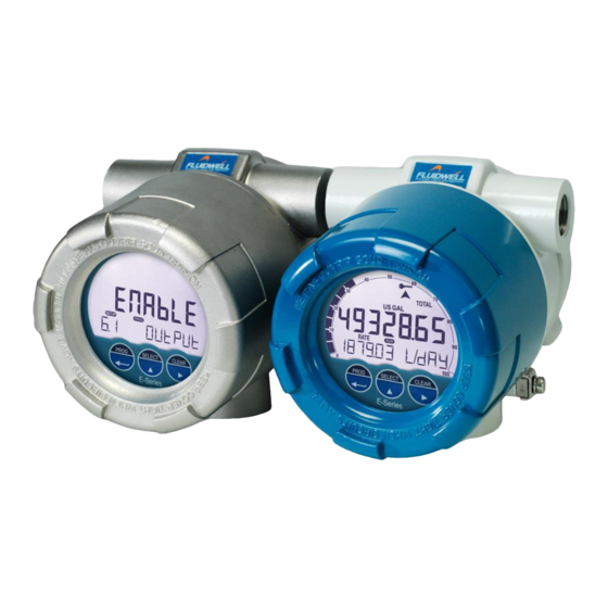
EXPLOSION PROOF FLOWRATE INDICATOR / TOTALIZER
Signal input flowmeter: pulse, NAMUR and coil
Signal outputs: Analog referenced flowrate and scaled or unscaled
pulse referenced total
Remote control: External reset with clear-lock
Options: HART communication and external reset
E-Series - Explosion proof indicators for hazardous areas.
E-Series - Explosion proof indicators for hazardous areas.
More info: www.fluidwell.com/eseries.
More info: www.fluidwell.com/eseries.
Advertisement
Table of Contents

Related Manuals for HART E018-P


Summary of Contents for HART E018-P
- Page 1 Signal outputs: Analog referenced flowrate and scaled or unscaled pulse referenced total Remote control: External reset with clear-lock Options: HART communication and external reset E-Series - Explosion proof indicators for hazardous areas. E-Series - Explosion proof indicators for hazardous areas.
-
Page 2: Safety Instructions
Compatibility). • Do connect a proper grounding to the housing as indicated if the E018-P is used on a ship, truck or other application with no ground. The earth lead between the housing and the removable terminal-block may never be removed. -
Page 3: About The Operation Manual
This operation manual describes the standard E018-P as well as most of the options available. For additional information, please contact your supplier. A hazardous situation may occur if the E018-P is not used for the purpose it was designed for or is used incorrectly. Please carefully note the information in this operating manual indicated by the pictograms: A "warning !"... -
Page 4: Table Of Contents
Label with thread sizes ......................44 Internal Labels........................45 Technical Specification ..................... 46 Problem Solving ......................49 HART communication ....................50 Declaration of Conformity ..................53 INDEX of this manual ........................54 List of figures in this manual ......................55... -
Page 5: Introduction
1 INTRODUCTION SYSTEM DESCRIPTION Functions and features The flowrate / totalizer model E018-P is an explosion proof microprocessor driven instrument designed to linearize the flowmeter’s flow curve and to show the flowrate, the total and the accumulated total. This product has been designed with a focus on: ▪... - Page 6 Flowrate levels as well as the minimum and maximum signal output can be tuned. Configuration The E018-P has been designed to be implemented in many types of applications. For that reason, a SETUP-level is available to configure your E018-P according to your specific requirements.
-
Page 7: Operational
Page 7 2 OPERATIONAL GENERAL INFORMATION This chapter describes the daily use of the E018-P. This instruction is meant for users / operators. • The E018-P may only be operated by personnel who are authorized and trained by the operator of the facility. All instructions in this manual are to be observed •... - Page 8 PROG – SELECT – CLEAR. They operate in the same manner as the optical keys, and when pressed, the optical keys are disabled for 30 seconds to prevent any interference. Fig. 5: Control panel, Push button operation FW-E018-P-M_v0203_03_EN.docx...
-
Page 9: Operator Information And Functions
For the Operator, the following functions are available: Display process values On the main screen, the primary process values of the E018-P are shown. By default, Total is shown on the upper-line of the display and Flowrate on the bottom line. -
Page 10: Operator Alarms
When an internal alarm condition occurs, the alarm-flag is shown on the display. After pressing the SELECT-key several times, the display will show the alarm code. Please see Appendix B: Problem solving for an explanation of the available alarm codes. ALARM FW-E018-P-M_v0203_03_EN.docx... -
Page 11: Configuration
Unlock the optical keys as described before. 3.2.1 ENTERING SETUP-LEVEL Configuration of the E018-P is done at SETUP-level, which can be reached at all times while the E018-P remains fully operational. At SETUP-level the display will deactivate the indicator and... - Page 12 The combination of the SELECT-key and CLEAR-key is used to select a negative value. When a value can also be entered as a negative number, pressing the SELECT- key and CLEAR-key simultaneously will toggle the ‘–‘ (minus) sign on and off. FW-E018-P-M_v0203_03_EN.docx...
- Page 13 Please keep a record of all settings for later reference. Use the control panel to return to OPERATE-level PROG-key In order to return to the operator level, press the PROG-key for three seconds. When no keys are pressed for 2 minutes, SETUP-level will be left automatically. FW-E018-P-M_v0203_03_EN.docx...
-
Page 14: Configuration Settings
Page 14 CONFIGURATION SETTINGS All settings of the E018-P can be set via the control panel. As an alternative, you can also use a HART communicator or the Remote Configuration Software which you can find on our website or through your supplier. - Page 15 COM-HART ADDRESS 0 – 63 LOOP CURRENT enable – disable LOOP TEST Off – set 4mA (fixed) – set 20mA (fixed) 10 OTHERS 10.1 MODEL E018-P 10.2 SOFTWARE VERSION xx:xx:xx 10.3 SERIAL NO xxxxxxx 10.4 PASSWORD 0000 – 9999 10.5 KEY LOCK enable –...
- Page 16 With this setting, you determine a minimum flow requirement thresh-hold, if during this time less than XXX-pulses (SETUP 2.5) are generated, the flowrate will be displayed as zero. The cut-off time has to be entered in seconds - maximum time is 999 seconds (about 15 minutes). FW-E018-P-M_v0203_03_EN.docx...
- Page 17 Pulse output menu (SETUP-menu 8). • For transistor / relay output functions: read SETUP-menu 8 – Pulse output. • The flowrate alarms are visible in HART. - A low alarm will set dev.statusbit 14.5 - A high alarm will set dev.statusbit 14.6 ALARM 3.1 FLOWZERO...
- Page 18 When the unit is only loop powered it cannot make use of the backlight. In that case an external supply is required. BL ALARM In case the E018-P generates a flowrate alarm, the backlight can be set to change to red. Following selections are available: OFF:...
- Page 19 EXPLANATION OF SETUP-MENU 5 – FLOWMETER 3.3.6 The E018-P is not equipped with an automatic unit conversion feature. This means that different K-Factors for Total and Flowrate must be entered manually. This gives you the possibility to have absolute freedom in configuring the various measurement units to your needs.
- Page 20 FLOWMETER SIGNAL The E018-P is able to handle several types of input signal. The type of flowmeter pickup / signal is selected with SETUP 5.1. The settings with LP are used to apply a build-in low-pass filter. See also chapter. 4.4.
- Page 21 LINEARIZATION With this setup function, you can easily enable / disable the linearization function. DECIMALS FREQUENCY This setting determines the number of decimals for the frequency entered. The following can be selected: 0 – 0.1 – 0.02 – 0.003 FW-E018-P-M_v0203_03_EN.docx...
- Page 22 The number of decimals displayed for RATE-MIN and RATE-MAX depend upon SETUP 2.3. However, if previously a value was entered that does not fit on the display (e.g. via the HART interface), the number of displayed decimals is reduced to fit the most significant digits on the display.
- Page 23 100 pulses per gallon: do enter 0.01 GAL (this means one pulse every 0.01 GAL, so 100 pulses per gallon). The following can be selected: 000.000 – 9999999 After pressing PROG, the decimal point will be flashing. The decimal position can be changed now by pressing the ▲-key. FW-E018-P-M_v0203_03_EN.docx...
- Page 24 Page 24 3.3.10 EXPLANATION OF SETUP-MENU 9 - COM-HART The E018-P can optionally be equipped with a communication interface using the HART protocol (Type CR). Please consult Appendix C for a more detailed explanation of the protocol, data types and available commands.
-
Page 25: Installation
Operating Manual before carrying out its instructions. • The E018-P may only be operated by personnel who are authorized and trained by the operator of the facility. All instructions in this manual are to be observed. -
Page 26: Mechanical Installation
• Possible electrostatic hazard – clean only with a moist cloth. Use only in fixed installations and do not place in areas with rapid airflow. DIMENSIONS – ENCLOSURE 4.3.1 Fig. 9: Dimensions – Aluminum / Stainless Steel enclosures FW-E018-P-M_v0203_03_EN.docx... - Page 27 0°; 90°; 180°; 270°, so the enclosure can be installed in four positions. The enclosure can be installed on a wall by using the mounting plate (accessory) or pipe mounted with the bracket and hose clamps (accessory). Fig. 10: Installation – Plate mounted Fig. 11: Installation – Pipe mounted FW-E018-P-M_v0203_03_EN.docx...
- Page 28 There may be no generation of heat in the added enclosure; • There may be no added electrical energy in the added enclosure; any energy which comes from the E-series is already taken into account in the E-series certificate. FW-E018-P-M_v0203_03_EN.docx...
-
Page 29: Electrical Installation
DO NOT OPEN WHEN AN EXPLOSIVE GAS ATMOSPHERE IS PRESENT. • Electro static discharge does inflict irreparable damage to electronics! Before installing or opening the E018-P, the installer has to discharge himself by touching a well-grounded object. • The E018-P must be installed in accordance with the EMC guidelines (Electro Magnetic Compatibility). - Page 30 The output relay (OR option) is of type SPST and has the following contact ratings: Load type & Voltage Current Maximum resistive load at 30 Vdc, 125 Vac or 250 Vac. Max. 2 A Maximum inductive load (for pilot duty applications) at 30 Vdc, 125 Vac or 250 Vac. Max. 0.5 A FW-E018-P-M_v0203_03_EN.docx...
- Page 31 • The output is protected against overload. In case of an overload also the functionality of the E018-P is affected! The voltage is selected with the two switches at the rear of the Main Electronics Module (MEM). The switches are located at the bottom center (type PD): Fig.
-
Page 32: Overview Of Terminal Connectors
Page 32 OVERVIEW OF TERMINAL CONNECTORS The following terminal connectors are available for the Main Electronics Module (MEM): Fig. 14: Terminals connectors MEM – standard and options FW-E018-P-M_v0203_03_EN.docx... -
Page 33: Terminal Connectors
Terminals R1, R3 and R5 are common ground (GND) terminals. • The output functionality of digital outputs D5 and D6 corresponds to the functionality of digital outputs D3 and D4 (respectively) • When retransmit mode is selected the minimum on and off-time is 50μs. FW-E018-P-M_v0203_03_EN.docx... - Page 34 The output functionality of digital outputs D5 and D6 corresponds to the functionality of digital outputs D3 and D4 (respectively). • When retransmit mode is selected, the relays are not activated. Fig. 17: Terminal connections – Mechanical relay outputs D5 – D6 FW-E018-P-M_v0203_03_EN.docx...
- Page 35 Fig. 18: Terminal connections – Coil signal input Pulse-signal NPN / NPN-LP The E018-P is suitable for use with flowmeters which have a NPN output signal. For reliable pulse detection, the signal should be above 1.4V or below 1.0V under all circumstances. It is advised to use a sensor which is normally open and is closed for a small time (less power consumption).
- Page 36 Page 36 Pulse-signal PNP / PNP-LP The E018-P is suitable for use with flowmeters which have a PNP output signal. 3.0V is offered on terminal S3 which has to be switched by the sensor to terminal S2 (SIGNAL). For reliable pulse detection, the signal should be above 1.4V or below 1.0V under all circumstances.
- Page 37 Page 37 NAMUR-signal The E018-P is suitable for flowmeters with a NAMUR signal. The standard E018-P-PX is not able to power the NAMUR sensor. If required the NAMUR sensor can be supplied via the 8.2V sensor supply (terminal P3), only available with power supply type PD. See paragraph 3.3.6 for more information.
- Page 38 The total loop resistance may not exceed 1000 Ohm and may not be less than 330 Ohm (at 30mA). This makes that the resistance of other loop-devices in total may not exceed 670 Ohm. E.g. 18Vdc allows 250 Ohm. Fig. 25: Terminal connections – Isolated 4-20mA analog output FW-E018-P-M_v0203_03_EN.docx...
- Page 39 Page 39 Terminal A1-A2; HART Communication – Type CR: The E018-P is suitable for connecting a HART master device. This HART master device is connected to Terminal A1 and Terminal A2 to enable HART communication with the unit. Optionally, a HART communicator can be connected in the loop as well, provided that a suitable resistance is inserted in the loop.
-
Page 40: Maintenance
“Safety rules, instructions and precautionary measures” in the front of this manual. • The E018-P may only be operated by personnel who are authorized and trained by the operator of the facility. All instructions in this manual are to be observed. -
Page 41: Open And Close The E-Series
(7). Note that the MEM goes off. 3. Disconnect the connectors (6) from the MEM (4). 4. Protect the connectors (6, 7) against the ingress of contamination. Keep the MEM (4) in a clean and safe location. FW-E018-P-M_v0203_03_EN.docx... - Page 42 2. Lock the flatcable connector (7) by hand and note that the MEM (4) comes on. 3. Hold the MEM (4) in the correct position for installation. Mind the wiring and carefully move the MEM (4) into the housing (1). FW-E018-P-M_v0203_03_EN.docx...
- Page 43 5.4.6 JOB CLOSE UP 1. Do a test of the optical keys to make sure the E018-P is ready for daily use. 2. Remove all tools, materials and equipment from the work area. 3. Make sure, the work area is clean.
-
Page 44: Labels
The E-series comes in temperature class T6. T6 classified versions consume 4.5 watts or less. Fig. 27: External label Certification Data LABEL WITH THREAD SIZES The thread sizes will be indicated on the label as per the drawings below. Fig. 28: Example external label Thread Sizes FW-E018-P-M_v0203_03_EN.docx... -
Page 45: Internal Labels
Label attached to the Basic Supply Module (BSM) – option PB. Fig. 30: Example Label on the Basic Supply Module (BSM) Label attached to the Relay Supply Module (RSM) – option (PB)-OR. Fig. 31: Example Label on the Basic Supply Module (BSM) FW-E018-P-M_v0203_03_EN.docx... -
Page 46: Technical Specification
Type Removable plug-in terminal strip. Wire max. 1.5 mm and 2.5 mm Data protection Type EEPROM backup of all settings. Backup of running totals every minute. Data retention at least 10 years. Password Configuration settings can be password protected. FW-E018-P-M_v0203_03_EN.docx... - Page 47 Maximum resistive load: 2A @ 250V AC / 30V DC. Maximum inductive load: 0,5A (pilot duty applications). • Requires 24 - 27V DC and supplied via P5 - P6. • Type OT remains available. • Not used in pulse retransmission mode. FW-E018-P-M_v0203_03_EN.docx...
- Page 48 Accuracy 12 bit. Error 0.03% @ 20°C (Typical 45ppm/°C). Can be scaled to any desired range. Communication (option) Functions Reading display information, reading / writing all configuration settings Type CR HART Communication protocol, Revision 7.0 Loop resistance Between 250 and 1100Ω Addressing Maximum 32 addresses...
-
Page 49: Problem Solving
Page 49 PROBLEM SOLVING In this appendix, several problems are included that can occur when the E018-P is going to be installed or while it is in operation. Flowmeter does not generate pulses Check: • Signal selection SETUP 5.1. •... -
Page 50: Hart Communication
HART - Highway Addressable Remote Transducer – is an industrial protocol that must be superimposed on a 4-20mA current loop signal. It is an open standard, and full details about HART can be obtained through the website of the FieldComm Group (previously HART Communication Foundation) at www.fieldcommgroup.org. - Page 51 The Flowrate value is permanently linked to the PV and the analog output. Device status information The E018-P returns its status in the device status byte available through command 48. When the status flag ‘more status available’ is set, command 48 can return the following status flags in its...
- Page 52 Page 52 Units The predefined units in HART are mapped to the E018-P totalizer and flowrate units as follows: Totalizer Setup unit Display icon DD unit Hart unit number M3/Cum US Gal I GAL Imp gal. Cuft Oil bbl met ton...
-
Page 53: Declaration Of Conformity
Page 53 DECLARATION OF CONFORMITY FW-E018-P-M_v0203_03_EN.docx... -
Page 54: Index Of This Manual
SETUP-level ..........11 signal ............20 terminal connectors ....... 32, 33 flowrate total cut-off time..........16 decimals ............ 15 decimals ............ 16 decimals k-factor ........21 measuring unit ........... 16 measuring unit ........... 15 Flowrate ............9 Total ............... 9 FW-E018-P-M_v0203_03_EN.docx... -
Page 55: List Of Figures In This Manual
Fig. 24: Terminal connections – External reset input Fig. 25: Terminal connections – Isolated 4-20mA analog output Fig. 26: Terminal connectors – Isolated 4-20mA analog output with HART devices Fig. 27: External label Certification Data Fig. 28: Example external label Thread Sizes Fig. - Page 56 Page 56 Notes: FW-E018-P-M_v0203_03_EN.docx...
- Page 57 Page 57 Notes: FW-E018-P-M_v0203_03_EN.docx...
- Page 58 SET ALARM operator LCD NEW 1 sec BACKLIGHT 100% BACKLIGHT ALARM BARGRAPH enabled RATESPAN 9999 FLOWMETER SIGNAL coil-lo LINEARIZE FREQUENCY 1 0.0Hz M-FACTOR 1.000000 FREQUENCY 2 0.0Hz M-FACTOR 1.000000 FREQUENCY 3 0.0Hz M-FACTOR 1.000000 FREQUENCY 4 0.0Hz M-FACTOR 1.000000 FW-E018-P-M_v0203_03_EN.docx...
- Page 59 RELAY 4 WIDTH 000 sec 0001000 AMOUNT COM-HART ADDRESS LOOP CURRENT enabled LOOP TEST OTHERS 10.1 MODEL E018-P E018-P E018-P 03:_ _:_ _ 10.2 SOFTWARE VERSION 10.3 SERIAL NO _ _ _ _ _ _ _ 10.4 PASSWORD 0000 10.5...
- Page 60 Page 60 Fluidwell B.V. FW-E018-P-M_v0203_03_EN.docx PO box 6 Voltaweg 23 Website: www.fluidwell.com 5460 AA Veghel 5466 AZ Veghel Find your nearest representative: www.fluidwell.com/representatives The Netherlands The Netherlands Copyright: 2019 - FW-E018-P-M_v0203_03_EN.docx...
Need help?
Do you have a question about the E018-P and is the answer not in the manual?
Questions and answers