Table of Contents

Subscribe to Our Youtube Channel
Related Manuals for Siemens SIMATIC OP7


Summary of Contents for Siemens SIMATIC OP7
- Page 1 control system Programme for chambers with µ PLC Instruction Handbook Angelantoni Industrie s.p.a. 06056 Massa Martana (Pg) Italy Tel. (++39) 075 8955.1 (a.r.) Fax (++39) 075 8955200 Internet:WWW.Angelantoni.it E-Mail:info@angelantoni.it 512976...
-
Page 2: Table Of Contents
CONTENTS 1 WARNINGS ............................. 3 2 THE OP7 SYSTEM ............................. 3 DESCRIPTION ..........................3 KEY FUNCTIONS ..........................4 BRIEF LIST OF THE MOST USED TERMINOLOGY ................5 START-UP ............................6 2.4.1 HOW TO SWITCH ON/OFF ....................7 HOW TO THE SET SOFTWARE ALARMS ..................7 OPERATION DIAGRAM ........................ -
Page 4: Warnings
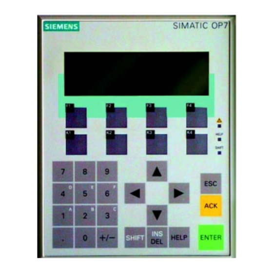
The system consists of a control panel equipped with a display, keyboard and function keys. This system enables temperature and humidity cycles to be carried out. The system can operate Manually or Automatically. SIMATIC OP7 SIEMENS Display This push-button may not be... -
Page 5: Key Functions
SIMATIC OP7 SIEMENS MICRO HELP SHIFT 0 +/- HELP ENTER SHIFT Main memory RAM work memory (volatile) The programmes set on the OP7 panel have to be memorised permanently in the MICRO PLC; if there is a black-out or if the machine is switched off, those programmes which have not been saved will be lost. -
Page 6: Brief List Of The Most Used Terminology
To erase a letter pinpointed by the cursor. To confirm a choice or a value that has been ENTER The letters will then run from right to left. inserted. If it is used together with SHIFT To read alarm signals and to carry out the relevant reset. -
Page 7: Start-Up
• Loop table This enables up to 10 repetitions of parts of a programme (series of segments or single segment) to be set. It is possible to carry out another nested loop within a loop; the former, however, must be part of the main loop. •... -
Page 8: How To Switch On/Off
Manual mode 2.4.1 HOW TO SWITCH ON/OFF When this key is pressed, the machine stops and restarts only in the A)By pressing key K1 manual mode. If the machine is operating automatically, please refer to paragraph 4.6. B)By pressing the lighted START/STOP push-button When this push-button is pressed, the machine stops and restarts either manually or automatically. -
Page 9: Operation Diagram
OPERATIONAL DIAGRAM SIEMENS SIMATIC OP7 HELP SHIFT 0 +/- SHIFT HELP ENTER Angelantoni Ind. Challenge 0.000 VISUALIZATION MANUAL SETTING GENERAL SETTINGS CYCLE MENU EDITA PRO- SAVES DELETES CURRENT GRAMME PROGRAMME PROGRAMME PROGRAMME CHECK LOADS CYCLE LOOP TABLE REPETITIONS PROGRAMME VISUALIZATION... -
Page 10: Manual Operation
MANUAL OPERATION In order to make the following instructions easier to understand, examples with the relevant values will be given. Operations that can be carried out in manual mode: HOW TO SET A VALUE HOW TO SET A CONTROLLED SLOPE - Controlled temperature slope setting (Example 20 ÷... - Page 11 Place the cursor as shown in order to set a humidity value %. Imp. temp. 80.00°C Imp. umid. 70.00 % If the chamber is not climatic, leave the value at zero If you enter the wrong number, you will still have to press ENTER and then re-digit ENTER the number.
-
Page 12: Test Start-Up
In some versions of the programme the writing in points (1), (2), (3), are replaced by: Water recharge: Dedicated contact 5 Not used: Dedicated contact 6 Not used: Dedicated contact 7 SP. hum. CTRL 1) When it is switched ON, the condensate water is recycled When it is switched OFF, the condensate water is drained off. -
Page 13: How To Set A Controlled Slope
HOW TO SET A CONTROLLED SLOPE Temperature Chart - Setting of a controlled temperature slope (Ex- Temp ample 20÷35°C) with an average gradient of °C 1°C per minute and 60% relative humidity - Setting of a humidity from 60 to 90% with a gradient of 2% per minute (in order to calculate the average gradient, that is the temperature rise or descent speed, please... - Page 14 Flashing cursor Temper. Set. 0.00°C To set the temperature ( Humid. Set. 0.00 % To set the humidity % ( (1) See the temperature range in the chapter entitled “Technical specifications” Place the cursor as shown in order to (2) See the humidity range in the chapter entitled “Technical specifications” set a temperature value Temp.
-
Page 15: Cycle Start-Up
CYCLE START-UP • Press this key to switch it off (led light switched off) If the machine has stopped: VISUALIZED ON THE DISPLAY: • Press this key to start the • The key led light is switched on. machine • The machine starts, reaches the set temperature value (20°C) and continues to operate along this value. - Page 16 1.00 °C min Temp. gr. Hum. gr. 0.00 RH%min • Enter the temperature gradient but leave the humidity gradient at 0 for the time being. If you enter the wrong number, you will still have to press ENTER and then re-digit ENTER the number.
-
Page 17: Step C
STEP C Set a controlled humidity slope from 60% to 90% with a gradient of 2%/min with a constant temperature and 60% RH humidity DISPLAY FUNCTIONS KEYS Temp • Wait for the chamber to reach the preset values, 35°C °C and 60% RH (Step A and Step B). - Page 18 To enable or disable tempera- ture control Temperature enab. Humidity enab. To enable or disable humidity control Temperature control is enabled. If you also wish to enable humdity control, move the cursor to the line below and use Temperature enab. SHIFT the same keys.
-
Page 19: Automatic Operation
AUTOMATIC OPERATION In order to make the following instructions easier to understand, a temperature and humidity cycle will be carried out. EXAMPLE CYCLE Maximum Constant humidity speed Example graph of humidity control Controlled humidity slope Ambient humdity Period of stabilization 1,5 2,5 2 1,5 Example graph of... -
Page 20: Example Cycle Table
EXAMPLE CYCLE TABLE Segment n° Duration ..1:0:0 2:0:0 1:30:0 2:30:0 2:0:0 2:0:0 1:30:0 0:0:5 0:0:0 1:30:0 Duration wait: CHANNEL 1 Control: Wait for set point Max speed Set point Gradient 0.00 0.00 0.00 0.28 0.00 0.21 0.00 0.70 0.00 0.00 0.00 Near set... -
Page 21: How To Set A Programme
HOW TO SET A PROGRAMME The cycle shown in the graph will be set as an example here below. • Place the software alarms into position (paragraph 2.5) • Place the hardware alarms into position (see machine handbook) FUNCTIONS KEYS DISPLAY This page is used to select the various functions to run the cycles and to start... - Page 22 SHIFT ENTER Channel 1 Control : ON Turn all the values to ON as shown Wait set point : ON Max speed : ON : 0.00 °C Set point : 0.00 °C/min Grad. : 1,00 °C Near set 1 (°C) To set segment Temperature 30°C At maximum speed...
- Page 23 In some versions of The rising dehumidification (optional) avoids the the programme the formation of condensate on the object to be Dehumidification : OFF writing of these fields tested. The chamber must be equipped from the are replaced by: start with this device. Vibrator : OFF Dedicated contact 1...
- Page 24 2 (°C) To set segment Temperature 30°C Duration 1h - Maintenance hh : mm : ss Durat. Wait duration : ON 1,5 2,5 Channel 1 Control : ON Wait set point : OFF Because the same temperature value Max speed :OFF is maintained : 30.00 °C...
- Page 25 3 (°C) To set segment Temperature 30°C Duration 2h - Maintenance hh : mm : ss Durat. Wait duration : ON 1,5 2,5 Channel 1 Control : ON Wait set point : OFF Because the same temperature value Max speed : OFF is maintained : 30.00 °C...
- Page 26 4 (°C) To set segment Temperature from 30°C to 55°C Duration 1.5h - slope - gradient 0,28°C/min hh : mm : ss Durat. : 30 Wait duration : ON Channel 1 Control : ON Wait set point : ON Because a controlled slope is set Max speed : OFF : 55.00 °C...
- Page 27 5 (°C) To set segment Temperature 55°C Duration 2,5h - Maintenance hh : mm : ss Durat. : 30 Wait duration : OFF Channel 1 Control : ON Wait set point : ON Because the same temperature value Max speed : OFF is maintained : 55.00 °C...
- Page 28 6 (°C) To set segment Temperature from 55°C to 30°C Duration 2h - slope - gradient 0.21°C/min hh : mm : ss Durat. : 00 : 0 Wait duration : ON Channel 1 Control : ON Wait set point : ON Because the same temperature value Max speed : OFF...
- Page 29 7 (°C) To set segment Temperature 30°C Duration 2h - Maintenance hh : mm : ss Durat. : 00 : 0 Wait duration : ON Channel 1 Control : ON Wait set point : OFF Because the same temperature value Max speed : OFF is maintained...
- Page 30 The following four segments are the same as 4,5,6,7 and therefore a repetition loop will be set later on. When segment 7 has been programmed, the procedure will pass on to segments 8,9,10,11 and then a repetition loop will be inserted. 8 (°C) Temperature from 30°C to 95°C To set segment...
- Page 31 When the temperature reaches 95°C, humidity control must be switched off, so a very short segment (9) has to be carried out that lasts only a few seconds (e.g. 5 secs.) 9 (°C) To set segment Temperature 95°C Duration 5 secs - Maintenance hh : mm : ss Durat.
- Page 32 10 (°C) To set segment Temperature from 95°C to 110°C Maximum speed hh : mm : ss Durat. 0 : 0 : 0 Wait duration : OFF Channel 1 Control : ON Wait set point : ON To carry out the segment at maximum Max speed : ON speed...
- Page 33 11 (°C) To set segment Temperature 110°C Maximum speeDuration 1.5h - Maintenance hh : mm : ss Durat. : 30 Wait duration : ON Channel 1 Control : ON Wait set point : ON Max speed : OFF because it is being maintained :110.00 °C Set point : 0.00 °C/min...
-
Page 34: Loop Table
LOOP TABLE To set a LOOP How to set the LOOP, a repetition of segments 4,5,6,7 This enables up to 10 repetitions of parts of a programme (series LOOP of segments or single segment) to be set. It is possible to carry out another nested loop within a loop; this, however, must form part of the main loop. -
Page 35: How To Save A Programme
HOW TO SAVE A PROGRAMME SIEMENS SIMATIC OP7 It is extremely important to save the programme in the main memory (MICRO PLC) in order to avoid accidental deletions due to blackouts or MICRO to the machine being switched off. 0 +/-... -
Page 36: How To Load And Carry Out A Programme
HOW TO LOAD AND CARRY OUT A PROGRAMME SIEMENS SIMATIC OP7 • The programme to be carried out must always be present in the work memory (OP7). • If the programme is not present in the work memory MICRO (OP7), it will have to be loaded from the MICRO PLC according to the following procedure. -
Page 37: How To Delete A Programme
HOW TO DELETE A PROGRAMME SIEMENS SIMATIC OP7 • A programme to be deleted can be removed from the MICRO PLC memory as follows: MICRO 0 +/- SHIFT HELP ENTER RAM work memory Cycles Menu Program edit : (1) Loop table... -
Page 38: Repetitons (How To Repeat A Programme)
REPETITIONS (HOW TO REPEAT A PROGRAMME) SIEMENS SIMATIC OP7 • An entire programme can be repeated automati- cally, starting from a specific programme. NB: The first segment must always be carried MICRO out at maximum speed. • Up to 9999 repetitions of the entire programme... -
Page 39: How To Check A Programme
HOW TO CHECK A PROGRAMME SIEMENS SIMATIC OP7 This option enables one or more segments of the programme being loaded into the memory to be MICRO checked. The data in the memory cannot be modified at this 0 +/- SHIFT... -
Page 40: How To Visualize A Programme
4.10 HOW TO VISUALIZE A PROGRAMME SIEMENS SIMATIC OP7 This option enables the state of the chamber to be visualized during executiuon of the cycle. MICRO • Load the programme (see § 4.6) 0 +/- SHIFT HELP ENTER RAM work memory... - Page 41 In some versions of the programme the writing of these fields are replaced by: Dehumidification : _ _ _ Dedicated contact 1 Vibrator : _ _ _ Dedicated contact 2 Specimens : _ _ _ Dedicated contact 3 U.V. lamp : _ _ _ Dedicated contact 4 Water recharge:...
-
Page 42: How To Visualize User Analog Inputs
4.11 HOW TO VISUALIZE USER ANALOG INPUTS A/I-1 _ _ _ _ _ _mV User device 1 voltage User _ _ _ _ _ _ _ _ Corresponding value 1 for the user A/I-2 _ _ _ _ _ _mV User _ _ _ _ _ _ _ _ A/I-3... -
Page 43: General Settings
GENERAL SETTINGS In order to set the alarm parameters, Press GENERAL SETTINGS please refer to paragraph 2.5 (HOW TO SET THE SOFTWARE ALARMS). Over temp _ _ _ Under t. _ _ _ These fields are present only in some versions of the programme. -
Page 44: Alarms
ALARMS WARNING! Each time an operation is carried out to eliminate an alarm, a RESET must be carried out by pressing the ACK key on the OP7 operator panel. If the cause of the alarm has not been eliminated, the message on the display will disappear, whereas the led light showing that an alarm has been triggered remains switched on.
Need help?
Do you have a question about the SIMATIC OP7 and is the answer not in the manual?
Questions and answers