Table of Contents
Advertisement
Quick Links
Installation, Operation and Maintenance
CONTENTS
SAFETY CONSIDERATIONS . . . . . . . . . . . . . . . . . . . . .1,2
INSPECTION . . . . . . . . . . . . . . . . . . . . . . . . . . . . . . . . . . . . . 2
GENERAL . . . . . . . . . . . . . . . . . . . . . . . . . . . . . . . . . . . . . . 2-6
CONTROLS DESCRIPTION . . . . . . . . . . . . . . . . . . . . 7-18
Microprocessor Control Board . . . . . . . . . . . . . . . . . . . 7
Inputs . . . . . . . . . . . . . . . . . . . . . . . . . . . . . . . . . . . . . . . . . . . . 7
Outputs . . . . . . . . . . . . . . . . . . . . . . . . . . . . . . . . . . . . . . . . . . 7
External Connections . . . . . . . . . . . . . . . . . . . . . . . . . . . . 7
Microprocessor PCB Battery . . . . . . . . . . . . . . . . . . . . . 7
Controller . . . . . . . . . . . . . . . . . . . . . . . . . . . . . . . . . . . . . . . . 7
Optional Pendant. . . . . . . . . . . . . . . . . . . . . . . . . . . . . . . . . 7
Infrared Receiver . . . . . . . . . . . . . . . . . . . . . . . . . . . . . . . . . 7
Self Diagnostics. . . . . . . . . . . . . . . . . . . . . . . . . . . . . . . . . . 7
Receiver Indicators. . . . . . . . . . . . . . . . . . . . . . . . . . . . . . . 7
PRE-INSTALLATION. . . . . . . . . . . . . . . . . . . . . . . . . . . . . 19
Unpack Unit . . . . . . . . . . . . . . . . . . . . . . . . . . . . . . . . . . . . . 19
Blank Off Pieces. . . . . . . . . . . . . . . . . . . . . . . . . . . . . . . . . 19
Positioning. . . . . . . . . . . . . . . . . . . . . . . . . . . . . . . . . . . . . . 19
Ceiling Opening Sizes . . . . . . . . . . . . . . . . . . . . . . . . . . . 19
Thermostat . . . . . . . . . . . . . . . . . . . . . . . . . . . . . . . . . . . . 19
INSTALLATION . . . . . . . . . . . . . . . . . . . . . . . . . . . . . . . 19-31
Hanger Bolts . . . . . . . . . . . . . . . . . . . . . . . . . . . . . . . . . . . . 19
Installation Guide . . . . . . . . . . . . . . . . . . . . . . . . . . . . . . . 19
Condensate Piping . . . . . . . . . . . . . . . . . . . . . . . . . . . . . . 20
Duct Collars . . . . . . . . . . . . . . . . . . . . . . . . . . . . . . . . . . . . . 20
Piping Installation . . . . . . . . . . . . . . . . . . . . . . . . . . . . . . . 20
Piping Insulation . . . . . . . . . . . . . . . . . . . . . . . . . . . . . . . . 20
Wiring. . . . . . . . . . . . . . . . . . . . . . . . . . . . . . . . . . . . . . . . . . . 21
Terminal Strip Connections . . . . . . . . . . . . . . . . . . . . . 21
Fascia Assembly . . . . . . . . . . . . . . . . . . . . . . . . . . . . . . . . 21
Pendant Assembly Installation . . . . . . . . . . . . . . . . . . 31
PRE-START-UP . . . . . . . . . . . . . . . . . . . . . . . . . . . . . . . 31-33
Pre-Start Checks . . . . . . . . . . . . . . . . . . . . . . . . . . . . . . . . 31
Control Circuit Checks . . . . . . . . . . . . . . . . . . . . . . . . . . 31
Sequence of Operation . . . . . . . . . . . . . . . . . . . . . . . . . . 33
OPERATION . . . . . . . . . . . . . . . . . . . . . . . . . . . . . . . . . . . . . 33
Cool Only Mode Settings . . . . . . . . . . . . . . . . . . . . . . . . 33
Heat Only Mode Settings . . . . . . . . . . . . . . . . . . . . . . . . 33
Auto Mode Settings . . . . . . . . . . . . . . . . . . . . . . . . . . . . . 33
Setting the Current Time . . . . . . . . . . . . . . . . . . . . . . . . 33
Programming the Unit . . . . . . . . . . . . . . . . . . . . . . . . . . . 33
CONTROLS . . . . . . . . . . . . . . . . . . . . . . . . . . . . . . . . . . . . . 34
Setting Jumper Links. . . . . . . . . . . . . . . . . . . . . . . . . . . . 34
Software Control . . . . . . . . . . . . . . . . . . . . . . . . . . . . . . . . 34
Main Control Functions . . . . . . . . . . . . . . . . . . . . . . . . . 34
Manufacturer reserves the right to discontinue, or change at any time, specifications or designs without notice and without incurring obligations.
Catalog No. 04-53420008-01
Instructions
Page
Printed in U.S.A.
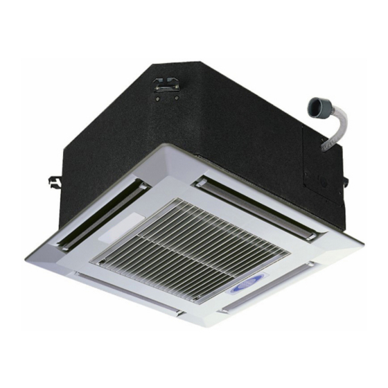
Hydronic Ceiling Cassettes
Alarms . . . . . . . . . . . . . . . . . . . . . . . . . . . . . . . . . . . . . . . . . . 34
CONTROLLER . . . . . . . . . . . . . . . . . . . . . . . . . . . . . .34,35
Master/Slave Operation . . . . . . . . . . . . . . . . . . . . . . . . . 34
Network Connection . . . . . . . . . . . . . . . . . . . . . . . . . . . . 35
MAINTENANCE . . . . . . . . . . . . . . . . . . . . . . . . . . . . . . . . . 35
Maintenance Schedule . . . . . . . . . . . . . . . . . . . . . . . . . . 35
Filter Removal and Cleaning. . . . . . . . . . . . . . . . . . . . . 35
Recommended Spares . . . . . . . . . . . . . . . . . . . . . . . . . . 35
DISASSEMBLY PROCEDURE. . . . . . . . . . . . . . . . . .35,36
Fan Removal . . . . . . . . . . . . . . . . . . . . . . . . . . . . . . . . . . . . 35
Condensate Tray Removal. . . . . . . . . . . . . . . . . . . . . . . 36
Condensate Pump Removal . . . . . . . . . . . . . . . . . . . . . 36
TROUBLESHOOTING . . . . . . . . . . . . . . . . . . . . . . . . 36-38
REPLACEMENT PARTS . . . . . . . . . . . . . . . . . . . . . . 39-41
SAFETY CONSIDERATIONS
Installing and servicing air-conditioning equipment can be
hazardous due to system pressure and electrical components.
Only trained and qualified service personnel should install and
service air-conditioning equipment.
Untrained personnel can perform basic maintenance, such
as cleaning and replacing filters. All other operations should be
performed by trained service personnel. When working on
air-conditioning equipment, observe safety precautions in liter-
ature and on tags and labels attached to the unit.
1. The equipment has been designed and manufactured to
meet international safety standards but, like any mechani-
cal/electrical equipment, care must be taken to obtain the
best results.
2. Service and maintenance of this equipment should only
be carried out by skilled personnel.
3. When working with any air-conditioning unit, ensure that
the electrical disconnect supplying the unit is switched off
prior to servicing or repair work and that there is no pow-
er to any part of the equipment.
4. Also ensure that there are no other power feeds to the unit
such as fire alarm circuits, building management system
(BMS) circuits, etc.
Pg 1
AIRSTREAM™
42WKN08-36
Page
4-13
Advertisement
Table of Contents

Related Manuals for Carrier AIRSTREAM 42WKN


Summary of Contents for Carrier AIRSTREAM 42WKN
-
Page 1: Table Of Contents
AIRSTREAM™ 42WKN08-36 Hydronic Ceiling Cassettes Installation, Operation and Maintenance Instructions CONTENTS Page Page • INDOOR FAN OPERATION SAFETY CONSIDERATIONS .....1,2 •... -
Page 2: Inspection
5. Electrical installation, start-up and maintenance work on this equipment should be undertaken by competent and IMPORTANT: Make sure the ceiling grid is supported sep- trained personnel in accordance with local relevant stan- arately from the appliance. The ceiling must not be sup- dards and codes of practice. - Page 3 Table 1 — 42WKN Physical Data 42WKN UNIT SIZE NOMINAL TONS COOLING CAPACITY (Btuh) 6,601 11,091 17,592 19,087 29,722 35,258 DIMENSIONS/WEIGHTS Height – Chassis/Fascia (in.) 11 / 1 11 / 1 13 / 1 13 / 1 (not additive) Width – Chassis/Fascia (in.) / 25 / 25 / 37...
- Page 4 25 3/16 CW Inlet CW Outlet HW Coil Inlet (Optional) HW Coil Outlet (Optional) Branch Duct Opening (x3) Fresh Air Intake (x2) Pump Inspection Port 25 3/16 Condensate Drain Control Panel 10. Mounting Bracket 1 11/16 10 11/16 1 1/8 2 3/4 2 3/4 9 13/16...
- Page 5 CW Coil Inlet CW Coil Outlet HW Coil Inlet (Optional) HW Coil Outlet (Optional) Fresh Air Intake (x3) Branch Duct Opening (x4) Pump Inspection Port Condensate Drain Control Panel 10. Mounting Bracket 11/16 2 5/8 9 1/2 2 3/4 32 3/8 7 13/16 3 1/8 2 3/4...
- Page 6 CW Coil Inlet CW Coil Outlet HW Coil Inlet (Optional) HW Coil Outlet (Optional) Fresh Air Intake (x3) Branch Duct Opening (x4) Pump Inspection Port Condensate Drain Control Panel 10. Mounting Bracket 49 3/16 a42-4321 2 1/4 2 5/8 11 1/2 4 3/4 9 13/16 3 1/8...
-
Page 7: Controls Description
CONTROLS DESCRIPTION A microprocessor mounted in a metal control box enclosure is used to control the entire unit operating functions with Microprocessor Control Board — The PCB (print- adjustments and settings being made from a hand-held IR ed circuit board) control board (see Fig. 4) relays control the transmitter or optional pendant. - Page 8 LEGEND — Alarm Relay — Central Processing Unit Factory-Installed AWG — American Wire Gage — Chilled Water BAT — Battery — Printed Circuit Board Field-Installed CPM — Condensate Pump Terminal Block Component Terminal a42-4333 Connected Path Fig. 5 — 42WKN Unit 2-Pipe Cooling Only System with Microprocessor Control Wiring Diagram, Sizes 08 and 12...
- Page 9 LEGEND — Alarm Relay — Central Processing Unit Factory-Installed AWG — American Wire Gage — Chilled Water BAT — Battery — Printed Circuit Board Field-Installed CPM — Condensate Pump — Vane Motor a42-4336 Terminal Block Component Terminal Connected Path Fig. 6 — 42WKN Unit 2-Pipe Cooling Only System with Microprocessor Control Wiring Diagram, Sizes 18 and 20...
- Page 10 LEGEND — Alarm Relay — Central Processing Unit Factory-Installed AWG — American Wire Gage — Chilled Water BAT — Battery — Printed Circuit Board Field-Installed CPM — Condensate Pump — Vane Motor a42-4327 Terminal Block Component Terminal Connected Path Fig. 7 — 42WKN Unit 2-Pipe Cooling Only System with Microprocessor Control Wiring Diagram, Sizes 33 and 36...
- Page 11 LEGEND — Alarm Relay — Chilled Water Factory-Installed AWG — American Wire Gage — Heat Relay BAT — Battery — Hot Water Field-Installed CPM — Condensate Pump — Printed Circuit Board a42-4332 Terminal Block CPU — Central Processing Unit Component Terminal Connected Path Fig.
- Page 12 LEGEND — Alarm Relay — Chilled Water Factory-Installed AWG — American Wire Gage — Heat Relay BAT — Battery — Hot Water Field-Installed A42-4323 CPM — Condensate Pump — Printed Circuit Board Terminal Block CPU — Central Processing Unit — Vane Motor Component Terminal Connected Path Fig.
- Page 13 LEGEND — Alarm Relay — Chilled Water Factory-Installed AWG — American Wire Gage — Heat Relay BAT — Battery — Hot Water a42-4328 Field-Installed CPM — Condensate Pump — Printed Circuit Board Terminal Block CPU — Central Processing Unit — Vane Motor Component Terminal Connected Path Fig.
- Page 14 LEGEND — Alarm Relay — Central Processing Unit Factory-Installed AWG — American Wire Gage — Hot Water BAT — Battery — Printed Circuit Board Field-Installed A42-4335 CPM — Condensate Pump — Valve Relay Terminal Block Component Terminal Connected Path Fig. 11 — 42WKN Unit 2-Pipe System with Heating/Cooling Changeover Aquastat and Microprocessor Control Wiring Diagram, Sizes 08 and 12...
- Page 15 LEGEND — Alarm Relay Factory-Installed — American Wire Gage — Battery Field-Installed A42-4339 — Condensate Pump Terminal Block — Central Processing Unit — Printed Circuit Board Component Terminal — Vane Motor Connected Path — Valve Relay Fig. 12 — 42WKN Unit 2-Pipe System with Heating/Cooling Changeover Aquastat and Microprocessor Control Wiring Diagram, Sizes 18 and 20...
- Page 16 LEGEND — Alarm Relay — Hot Water Factory-Installed AWG — American Wire Gage — Printed Circuit Board BAT — Battery — Vane Motor Field-Installed CPM — Condensate Pump — Valve Relay A42-4329 Terminal Block CPU — Central Processing Unit Component Terminal Connected Path Fig.
- Page 17 8-507_1 5 ON/SEND: Pressing this button will switch the unit on and transmit the system settings. TRANSMIT INDICATOR: MODE: This symbol will flash when the system settings are transmitted. Pressing this button will cycle through ON/SEND the mode options, COOL, AUTO, DRY, FAN &...
- Page 18 a42-4040 Fig. 16 — Infrared Receiver LEGEND Unit off, timer operation off, indoor fan Unit off, timer operation on, indoor fan off, cooling and heating off. off, cooling and heating off. Indicator Off Indicator On Indicator Flashing Unit on, timer operation off, indoor fan Unit on, timer operation off, indoor fan on, cooling and heating off.
-
Page 19: Pre-Installation
Installation Guide — An installation guide is included 30 in. a42-4049 in the Carrier Owner Information packet provided with the MAX. unit. Prepare the installation guide by folding the flat metal piece, by hand, along the perforations as shown in Fig. 20. -
Page 20: Condensate Piping
a42-4021 a42-4023 Fig. 23 — Condensate Piping Fig. 20 — Setting Up Installation Guide 5. Condensate piping must not be installed where it may be exposed to freezing temperatures. a42-4024 Duct Collars — Branch duct and fresh air duct collars can be attached to the unit chassis by following the steps below: 1. -
Page 21: Wiring
Wiring Table 5 — Electrical Data for Units with Optional Step-Up Transformer WARNING UNITS WITH OPTIONAL STEP-UP TRANSFORMER* 42WKN Recommended UNIT SIZE V-Ph-Hz Disconnect power supply before making wiring connec- Fuse (Amps) tions to prevent electrical shock and equipment damage. 08,12 115-1-60 All appliances must be wired strictly in accordance with... - Page 22 NOTE: Fan is wired to medium speed as a default. To change the default LEGEND fan speed, adjust wiring in the field. Factory-provided electro-mechanical — Alarm Relay thermostats are for single speed fan operation only. Factory-Installed — American Wire Gage —...
- Page 23 NOTE: Fan is wired to medium speed as a default. To change the default LEGEND fan speed, adjust wiring in the field. Factory-provided electro-mechanical — Alarm Relay thermostats are for single speed fan operation only. Factory-Installed — American Wire Gage —...
- Page 24 NOTE: Fan is wired to medium speed as a default. To change the default LEGEND fan speed, adjust wiring in the field. Factory-provided electro-mechanical — Alarm Relay thermostats are for single speed fan operation only. Factory-Installed — American Wire Gage —...
- Page 25 NOTE: Fan is wired to medium speed as a default. To change the default LEGEND fan speed, adjust wiring in the field. Factory-provided electro-mechanical — Alarm Relay thermostats are for single speed fan operation only. Factory-Installed — American Wire Gage —...
- Page 26 NOTE: Fan is wired to medium speed as a default. To change the default LEGEND fan speed, adjust wiring in the field. Factory-provided electro-mechanical — Alarm Relay thermostats are for single speed fan operation only. Factory-Installed — American Wire Gage —...
- Page 27 NOTE: Fan is wired to medium speed as a default. To change the default LEGEND fan speed, adjust wiring in the field. Factory-provided electro-mechanical — Alarm Relay thermostats are for single speed fan operation only. Factory-Installed — American Wire Gage —...
- Page 28 NOTE: Fan is wired to medium speed as a default. To change the default LEGEND fan speed, adjust wiring in the field. Factory-provided electro-mechanical — Alarm Relay thermostats are for single speed fan operation only. Factory-Installed — American Wire Gage —...
- Page 29 NOTE: Fan is wired to medium speed as a default. To change the default LEGEND fan speed, adjust wiring in the field. Factory-provided electro-mechanical — Alarm Relay thermostats are for single speed fan operation only. Factory-Installed — American Wire Gage —...
- Page 30 NOTE: Fan is wired to medium speed as a default. To change the default LEGEND fan speed, adjust wiring in the field. Factory-provided electro-mechanical — Alarm Relay thermostats are for single speed fan operation only. Factory-Installed — American Wire Gage —...
-
Page 31: Pendant Assembly Installation
The fascia can now be unpacked for fitting to the unit chas- 4. Hold the bottom of the pendant controller at the top of the wall bracket and slide the controller down the bracket to sis. Ensure the black fir tree fasteners holding the fascia poly- styrene are pushed in firmly in case of transit vibration. - Page 32 The units are now ready for the system balance to be cooling. performed. a42-4028 CASSETTE START UP SHEET NOTE: Any feedback may be submitted by fax to either the sale engineer or to the local Carrier office. Fig. 37 — Start-Up Sheet Example...
-
Page 33: Sequence Of Operation
Sequence of Operation 2. Press either + or - button within the CLK/TIMER area, the hours of the current time should now start to flash. ELECTRO-MECHANICAL CONTROLS — A 24-v signal 3. Use the + or - button to change the hour setting. Press from the thermostat to terminal G supplies power to the blower CLK/TIMER button once to enter the selected hour. -
Page 34: Controls
CONTROLS TEMPERATURE CONTROL — The controller will switch heating or cooling loads in order to maintain the temperature Setting Jumper Links set point. The deadband is programmed to 4 F. Under normal operation, cooling or heating will be activated at the limits of WARNING the deadband and will continue to operate until set point is achieved. -
Page 35: Network Connection
• In the event of the network cable being severed or com- Filter Removal and Cleaning munications between master and slaves being lost for 1. Disconnect power. any reason, the slave units will revert to stand alone con- 2. Unclip the catches along the edge of each grille and allow trol after six minutes without instruction from the master them to hang from the fascia by the molded plastic hinges unit. -
Page 36: Condensate Tray Removal
Condensate Tray Removal Condensate Pump Removal 1. Unclip the grille catches and remove the grille(s) from the 1. Disconnect the condensate pump and float switch wires fascia. from inside the electrical panel. 2. Remove the fascia by loosening the fascia mounting bolts 2. - Page 37 Table 6 — Troubleshooting PROBLEM POSSIBLE CAUSE POSSIBLE SOLUTION Red Alarm LED Flashing at 1-Second Faulty float switch See Condensate High Level section. Intervals (Microprocessor Units Only) Fan trip See Fans Will Not Run section. Indoor coil sensor failure After checking the above, use the unit wiring schematic to iso- (Connected to microprocessor termi- late the indoor coil sensor and measure the resistance.
- Page 38 Table 6 — Troubleshooting (cont) PROBLEM POSSIBLE CAUSE POSSIBLE SOLUTION Water Leaking from Unit Condensate plug loose or missing Check that the rubber condensate plug is securely fitted to the (also See Condensate High Level underside of the unit’s polystyrene drip tray. On some models Section) this is located underneath the fascia support rails on the pump side of the unit.
-
Page 39: Replacement Parts
This information can be found on the serial plate attached to the unit. See Fig. 39. CEILING CASSETTE UNIT MADE IN U.S.A. When a component part fails, contact your local Carrier rep- Unit Type: HOT WATER COIL: resentative to order a replacement part. See Fig. 40 and 41 for... - Page 40 a42-4032 DESCRIPTION DESCRIPTION Cassette Chassis Air Deflector Vanes (4) Chilled Water Coil Filter Electric Heater Element Assembly Fascia Assembly Condensate Tray Receiver (Microprocessor Only) Condensate Tray Supports (2) Terminal Rail, Relays and Timer Condensate Pump Control Box Lid High Level Switch Control Box Condensate Pump Assembly (Shown Inverted) PCB Controller (Microprocessor Only)
- Page 41 a42-4144 DESCRIPTION DESCRIPTION Cassette Chassis Vane Cooling Coil Vane Motor Assembly Condensate Tray Filter Condensate Tray Support Fascia High Level Switch (Shown Inverted) Remote Handset Condensate Pump (Shown Inverted) Control Box Lid Fan and Motor Assembly Control Box PCB Fan Inlet Ring Control Box Grille Coil Bracket...
-
Page 44: Form 42Wkn-7Si Pg
© Carrier Corporation 2013 Manufacturer reserves the right to discontinue, or change at any time, specifications or designs without notice and without incurring obligations. Catalog No. 04-53420008-01 Printed in U.S.A. Form 42WKN-7SI Pg 44 4-13 Replaces: 42WKN-6SI...
Need help?
Do you have a question about the AIRSTREAM 42WKN and is the answer not in the manual?
Questions and answers