
Related Manuals for Kramer VW-4


Summary of Contents for Kramer VW-4
- Page 1 USER MANUAL MODEL: VW-4 4 Output Video-Wall Driver P/N: 2900-301487 Rev 1 www.kramerAV.com...
-
Page 2: Table Of Contents
Kramer Electronics Ltd. Contents Introduction Getting Started Overview Typical Applications Defining VW-4 4 Output Video-Wall Driver Mounting VW-4 Connecting VW-4 Connecting to VW-4 via RS-232 Connecting via Ethernet Configuring VW-4 Configuring SETUP DIP-Switches Using the VW-4 App Adjusting the Video-Wall Image... -
Page 3: Introduction
Kramer Electronics Ltd. Introduction Welcome to Kramer Electronics! Since 1981, Kramer Electronics has been providing a world of unique, creative, and affordable solutions to the vast range of problems that confront the video, audio, presentation, and broadcasting professional on a daily basis. In recent years, we... -
Page 4: Overview
European Advanced Recycling Network (EARN) and will cover any costs of treatment, recycling and recovery of waste Kramer Electronics branded equipment on arrival at the EARN facility. For details of Kramer’s recycling arrangements in your particular country go to our recycling pages at www.kramerav.com/support/recycling. -
Page 5: Typical Applications
Stock market displays • Building lobbies • Corporate offices • In-store retail promotion • Convention and trade shows. Controlling your VW-4 Control your VW-4 via: • DIP-switch settings – for basic video-wall configuration. • VW-4 app, via the Ethernet or RS-232. -
Page 6: Defining Vw-4 4 Output Video-Wall Driver
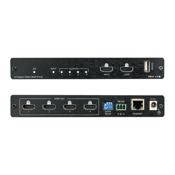
ETHERNET RJ-45 Connect to a PC via a LAN to setup and monitor the VW-4 via the Connector configuration app. 5V DC Connector Connect to the supplied power adapter. VW-4 – Defining VW-4 4 Output Video-Wall Driver... -
Page 7: Mounting
Kramer Electronics Ltd. Mounting VW-4 This section provides instructions for mounting VW-4. Before installing, verify that the environment is within the recommended range: • Operation temperature – 0 to 40C (32 to 104F). • Storage temperature – -40 to +70C (-40 to +158F). - Page 8 VW-4 (1-2) is HDMI OUT 2 on that device. Always switch off the power to each device before connecting it to your VW-4. After connecting your VW-4, connect its power and then switch on the power to each device. Figure 2: Connecting to the VW-4...
-
Page 9: Connecting
Kramer Electronics Ltd. Connecting to VW-4 via RS-232 You can connect to VW-4 via an RS-232 connection using, for example, a PC. VW-4 features an RS-232 3-pin terminal block connector allowing the RS-232 to control VW-4. Connect the RS-232 terminal block on the rear panel of... - Page 10 (TCP/IPv4) depending on the requirements of your IT system. 5. Click Properties. The Internet Protocol Properties window relevant to your IT system appears as shown in Figure 4 Figure Figure 4: Internet Protocol Version 4 Properties Window VW-4 – Connecting VW-4...
-
Page 11: Configuring
You can connect the Ethernet port of VW-4 to the Ethernet port on a network hub or using a straight-through cable with RJ-45 connectors. Configuring Ethernet Port You can set the Ethernet parameters via the embedded webpages. VW-4 – Connecting VW-4... -
Page 12: Configuring Setup Dip-Switches
Image appears on all displays. (Each display shows the full image). VW-4 Device 2x2 wall (0) 4x1 wall (0) 1x4 wall (0) Three VW-4 Devices 3x3 wall, first unit (0) 3x3 wall, second unit (1) 3x3 wall, third unit (2) VW-4 – Configuring VW-4... -
Page 13: Using The Vw-4 App
VW-4 devices. Download app from www.kramerav.com/product/VW-4#Tab_Resources). VW-4 app enables performing the following actions: • Connecting VW-4 Devices to the Network on page 12. • Configuring Device Settings on page 15. • Configuring Device Layout on page 21. - Page 14 Set each device with a unique IP address. You can do this by connecting a device to the App and changing its IP address (see Updating Network Settings on page 14). To Connect the video-wall VW-4 devices (for example, a 3x2 video-wall, using two devices): 1. Connect all the video-wall VW-4 devices to your network, making sure that each has a unique IP address.
- Page 15 RS-232 ports on your PC. Figure 8: Connection Window 4. Select a connected device under All Units and click The selected device moves to the Selected Units area. 5. Move other connected devices. Figure 9: Selected Devices under Selected Units VW-4 – Configuring VW-4...
- Page 16 Video-wall devices are connected. Updating Network Settings Change the IP address and other Network settings via P3K commands (see Protocol 3000 Commands on page 31) or via the VW-4 App. When changing Network settings, the device should be disconnected. VW-4 – Configuring VW-4...
- Page 17 16. • Updating the Firmware on page 17. • Performing Factory Reset on page 18. • Viewing Network Settings on page 18. • Defining Input Settings on page 18. • Defining Output Settings on page 20. VW-4 – Configuring VW-4...
- Page 18 2. Place cursor next to the ID. Figure 12: ID-NAME List 3. Change the ID number for each device and press ENTER on your PC. Figure 13: ID-NAME Changed The device ID number has changed and is saved. VW-4 – Configuring VW-4...
- Page 19 4. Connect the memory stick (USB) to SERVICE USB connector 5. Click OK. The device disconnects and the firmware is upgraded. 6. Reconnect the device and make sure that the firmware revision has changed. Firmware is updated. VW-4 – Configuring VW-4...
- Page 20 Manage the EDID and HDCP settings. To define input settings: 1. Select the Settings tab and then click Input tab. Figure 16: Input Settings 2. View the input signal status. Sync is green if a valid input is detected. VW-4 – Configuring VW-4...
- Page 21 You can copy the EDID from the display on one of the outputs (Out 1-4); select the manually uploaded EDID (User); or select a factory programmed 4K or 1080p EDID. Figure 17: Input Settings – EDID Options 4. Set HDCP to Enable/Disable and then click Save. Input Settings are defined. VW-4 – Configuring VW-4...
- Page 22 5. Set the status for each output (sink is green if a valid output is detected): ▪ View HDCP output status. ▪ Set HDCP status to: Follow In or Follow Out. ▪ Click Save per output. Output settings are defined. VW-4 – Configuring VW-4...
- Page 23 • Viewing the DIP-Switch Setup on page 24. Defining Video-Wall Size Video-wall size is defined by the number of its columns and rows. To define the wall size: 1. Select Layout tab. Figure 19: Layout Tab VW-4 – Configuring VW-4...
- Page 24 2. Set the video-wall size, in one of the following ways: ▪ Selecting Column and Row numbers (for example, 3 x 2). Figure 20: Layout Tab – 3x2 Video-wall Setting ▪ Clicking Quick Selection for common video-wall configurations. Figure 21: Quick Selection Video-wall Layout VW-4 – Configuring VW-4...
- Page 25 2. Click Bezel Off to set its status. Bezel status changes to On. Figure 23: Bezel Status On 3. Enter horizontal and vertical bezel corrections (in pixels) as required for the defined video-wall setting. Bezel corrections are defined. VW-4 – Configuring VW-4...
-
Page 26: Adjusting The Video-Wall Image
For these “non-square” wall sizes, make sure to manipulate the aspect ratio of the input image to perfect it for the proportions of the picture on the output. Figure 26: Correct Aspect Ratio on Output Image VW-4 – Configuring VW-4... -
Page 27: Upgrading Firmware
Kramer Electronics Ltd. Upgrading Firmware Upgrade the firmware via the app (see Updating the Firmware on page 17), using the VW-4 SERVICE USB port VW-4 – Upgrading Firmware... -
Page 28: Technical Specifications
Shipping Dimensions (W, D, H) 35.1cm x 21.2cm x 7.2cm (13.8" x 8.4" x 2.8") Net Weight 0.9kg (1.9lbs) Shipping Weight 1.4 kg (3.1lbs) approx. Accessories Included Power adapter and cord Specifications are subject to change without notice at www.kramerav.com VW-4 – Technical Specifications... -
Page 29: Default Communication Parameters
Modeline...."1920x1200" 154.000 1920 1968 2000 2080 1200 1203 1209 1235 +hsync -vsync Standard timings supported 720 x 400p at 70Hz - IBM VGA 640 x 480p at 60Hz - IBM VGA 640 x 480p at 75Hz - VESA VW-4 – Technical Specifications... - Page 30 EDID screen size..No additional info 3D formats supported..Not supported Data payload..... 030C001000B83C2F006001030400000000000000000000 CE vendor specific data (VSDB) IEEE registration number. 0xC45DD8 CEC physical address..0.1.7.8 Supports AI (ACP, ISRC).. Yes Supports 48bpp... No Supports 36bpp... No VW-4 – Technical Specifications...
- Page 31 YCbCr 4:2:0 capability map data Data payload..... 0F0012 Report information Date generated... 21/06/2021 Software revision..2.91.0.1043 Data source....File - NB: improperly installed Operating system..10.0.18362.2 Raw data 00,FF,FF,FF,FF,FF,FF,00,2D,B2,CC,0F,01,00,00,00,2D,1E,01,03,80,0C,09,78,0A,1E,AC,98,59,56,85,28, 29,52,57,A5,4B,00,81,C0,81,80,A9,C0,A9,40,D1,C0,71,4F,D1,00,81,00,08,E8,00,30,F2,70,5A,80,B0,58, 8A,00,A0,5A,00,00,00,1E,28,3C,80,A0,70,B0,23,40,30,20,36,00,A0,64,00,00,00,1A,00,00,00,FC,00,56, 57,2D,34,0A,20,20,20,20,20,20,20,20,00,00,00,FD,00,17,3D,0F,88,3C,00,0A,20,20,20,20,20,20,01,7A, 02,03,41,F0,50,10,05,20,22,04,03,13,14,1F,61,5D,5F,66,62,64,12,23,09,07,07,83,01,00,00,77,03,0C, 00,10,00,B8,3C,2F,00,60,01,03,04,00,00,00,00,00,00,00,00,00,00,67,D8,5D,C4,01,78,80,03,E3,0F,00, 12,02,3A,80,18,71,38,2D,40,58,2C,45,00,A0,5A,00,00,00,1E,56,5E,00,A0,A0,A0,29,50,30,20,35,00,A0, 5A,00,00,00,1A,00,00,00,00,00,00,00,00,00,00,00,00,00,00,00,00,00,00,00,00,00,00,00,00,00,00,CB VW-4 – Technical Specifications...
-
Page 32: Protocol 3000
(<…>) and must be separated by a period (.). The command framing varies according to how you interface with VW-4. The following figure displays how the # command is framed using terminal communication software (such as Hercules): VW-4 –... -
Page 33: Protocol 3000 Commands
TCP to port 12457: #ETH-PORTport_type,port_id<CR> (0 – 65535) #ETH-PORT0,12457<CR> FEEDBACK If the port number you ~nn@ETH-PORTport_type,port_id<CR><LF> enter is already in use, an error is returned. The port number must be within the following range: 0-(2^16-1). VW-4 – Protocol 3000... - Page 34 Get command list or help COMMAND Get the command list: for specific command. #HELP<CR> #HELP<CR> command #HELPcmd_name<CR> To get help for FEEDBACK AV-SW-TIMEOUT: 1. Multi-line: HELPav-sw-timeout<CR> ~nn@Devicecmd_name,cmd_name…<CR><LF> To get help for command use: HELP (COMMAND_NAME)<CR><LF> ~nn@HELPcmd_name:<CR><LF> description<CR><LF> USAGE:usage<CR><LF> VW-4 – Protocol 3000...
- Page 35 RS-232 protocol port, if available. For proper settings consult your network administrator. For Backward compatibility, the parameter can be omitted. In this case, the Network ID, by default, is 0, which is the Ethernet control port. VW-4 – Protocol 3000...
- Page 36 2 – slow out_index – Number that indicates SHOW-OSD Set the OSD of selected COMMAND Set the OSD of selected channel. channel: #SHOW-OSDout_index,switch<CR> the specific output: #SHOW-OSD1,1<CR> FEEDBACK switch – On/Off ~nn@SHOW-OSDout_index,switch<CR><LF> 0 – Off 1 – On VW-4 – Protocol 3000...
- Page 37 FEEDBACK 1 to 8 ~nn@WALL-LAYOUTok<CR><LF> – Number of columns: h_value WALL- Get the video-wall layout. COMMAND Get the video-wall layout: LAYOUT? #WALL-LAYOUT?<CR> 1 to 8 #SHOW-OSD?<CR> – Number of rows: v_value FEEDBACK 1 to 8 ~nn@WALL-LAYOUTh_value,v_value<CR><LF> VW-4 – Protocol 3000...
-
Page 38: Result And Error Codes
(Reserved) ERR_RESERVED_8 (Reserved) ERR_RESERVED_9 (Reserved) ERR_RESERVED_10 (Reserved) ERR_RESERVED_11 (Reserved) ERR_RESERVED_12 (Reserved) ERR_EDID_CORRUPTED EDID corrupted ERR_NON_LISTED Device specific errors File has the same CRC – not changed ERR_SAME_CRC ERR_WRONG_MODE Wrong operation mode ERR_NOT_CONFIGURED Device/chip was not initialized VW-4 – Protocol 3000... - Page 39 This limited warranty gives you specific legal rights, and you may have other rights which vary from country to country or state to state. This limited warranty is void if (i) the label bearing the serial number of this product has been removed or defaced, (ii) the product is not distributed by Kramer Electronics or (iii) this product is not purchased from an authorized Kramer Electronics reseller.
- Page 40 SAFETY WARNING Disconnect the unit from the power supply before opening and servicing For the latest information on our products and a list of Kramer distributors, visit our website where updates to this user manual may be found. We welcome your questions, comments, and feedback.
Need help?
Do you have a question about the VW-4 and is the answer not in the manual?
Questions and answers