
Related Manuals for Inscape Data MPEG4


Summary of Contents for Inscape Data MPEG4
- Page 1 Quick Reference Guide Rev.A1. (November 2006)
- Page 2 Please check to make sure the following items are in the box. Components Description Remarks AirGoggle NVC 300 AirGoggle NVC 300 Network Camera Input : 100~250V 50-60Hz Power adapter Standard Power Output : 7 ~23V, 8W AC power cable AC 250V, 10A~16A Cable for analog video output from Video cable camera module inside of network camera...
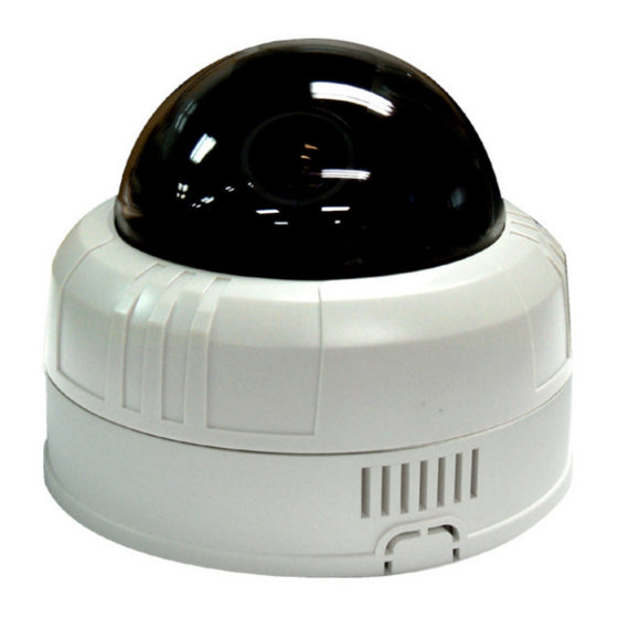
- Page 3 Figure 2-1. External and inner views of NVC300 POWER: Status indicator on the RJ45 port shows the status of the NVC. 1 Green: Green color indicates that the camera is in normal operation mode 2 Red: RED color indicates that the camera is in abnormal condition. Rev.A.1(November 2006)
- Page 4 2.3.2. Bottom view and Cable Harness Figure 2-2. Rear views and Cable of NVC 300 MIC/LINE IN: Interfaces Connect external audio source or microphone. LINE OUT: Interface to connect external speaker with amplifier 10BaseT: 10Mbps Ethernet interface for NVC RS-232C: For Debugging and factory use only (Not Present on most models) DC Power: DC 7-23V power supply to the unit (May not use this when power can be delivered through Ethernet port by PoE module.) Sensor In/Relay Out: Used for connecting sensor and alarm devices to the camera...
- Page 5 For further information on LAN, xDSL, and cable modem connections, please refer to the user manual in the CD provided with the product. In order to check the functionality of the product, please follow the 3 steps below: ① Connect the installation computer and the NVC product via a crossover Ethernet cable. ②...
- Page 6 Insert the product CD provided into the CD-ROM drive of the installation PC and select “2.IP- installer Software\IPInstaller_V2_1_3_English\install.bat”; the IP-Installer program will be automatically installed. ① Double-click the IP-Installer icon ( ) to start the IP-Installer. If using Window98SE, press “Refresh” button after starting the IP Installer.
- Page 7 Fig 2-5 Mode after double-click of MAC Address Refresh button MAC Address Fig 2-4 IP Installer’s Initial Mode ④ Double-click the MAC address on IP-Installer. Default network setup parameters are displayed on the right side of the screen as shown in Fig 2-5. According to the combinations of network type and IP allocation methods, “Network Mode”...
- Page 8 Fixed IP is required in “LAN Static” mode. Select “LAN Static” and insert “IP address” and “subnet mask” as shown in Fig 2-6. Subnet values of both the install PC and the product must be consistent and only the last portion of IP addresses of them should be different.
- Page 9 ① Start the software by double-clicking the icon, , on your windows desktop. The NVR100 software is shown in Fig 3-1. ②The NVR100 is designed to display 16 channels simultaneously. user customize the display mode accordingly to fit their needs. (Refer to NVR100 user’s Guide for more detail.) Fig 3-1 NVR100 Initial Mode Camera assignment Button...
- Page 10 Fig 3-3 Showing Live Images via NVR100 The NVC is designed to be accessed via your favorite web browser in addition to the NVR100 software. In order to access the unit, you must type in the appropriate IP address in the browser. Fig 3-4 is an example of the web interface.
- Page 11 AirGoggle™ ™ ™ ™ NVC 300 100BaseT Ethernet Connector Ethernet Cable (100 Meter Maximum) To Camera LAN Cable to Hub Power over Ethernet Module Adapter 12V DC CAUTION !! This PoE module will ONLY work with the AirGoggle NVC Camera. Please DO NOT use the PoE with other products.
Need help?
Do you have a question about the MPEG4 and is the answer not in the manual?
Questions and answers