
Related Manuals for Inscape Data AirGoggle NVC360


Summary of Contents for Inscape Data AirGoggle NVC360
- Page 1 Quick Install Guide AirGoggle™ IP Video Camera QUICK INSTALL GUIDE Rev 0.2 April 2009 Corporate Headquarters http://www.inscapedata.com Inscape Data Corporation Tel: 408 935-8500 1611 South Main Street 1-888-267-4507 Milpitas, CA 95035 Fax: 408 935-8900...
- Page 2 Please check to make sure the following items are in the box. Components Description Remarks AirGoggle NVC360 AirGoggle NVC360 Network Camera Input : 100~250V 50-60Hz Power adapter Standard Power Output : 12VDC / 3.33A AC power cable AC 250V, 10A~16A...
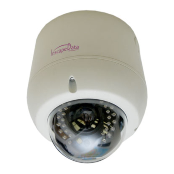
- Page 3 ○ ○ ○ ○ ○ ○ ○ ○ Figure 2-1. External and inner views of NVC360 1. Surface mount adaptor 2. Cap screw (PT3/4, 1EA) 3. Main body 4. Focus handle 5. Zoom handle 6. Tilt rotation 7. Horizontal rotation 8.
-
Page 4: Dip Switch Setting
1.3.2. Dip Switch Setting – LED/H –– VIDEO DC LEVEL DIP SWITCH SENSITIVITY A. DIP SWITCH SETTING -. FLK : Flickerless ON/OFF -. BLK : BLC ON/OFF -. LED/H : IR LED Illumination High power... - Page 5 1.3.3. Preparations for the installation Ceiling Mount Type 1. Fix the surface mount adaptor with 4pcs of screws on the place where you want to install. (FIG. 5) When you use pipe, please note the standard size of pipe. (FIG.6) 2.
- Page 6 The setup in this guide utilizes a crossover cable connection between the NVC units and installation computer as shown in figure 2-1 for easy installation and demonstration of basic feature sets. The NVC supports network configurations including LAN, ADSL modem, and cable modems including IP sharing devices.
- Page 7 ② Apply power to the NVC product and connect it to the installation PC with the crossover LAN cable as shown in Figure 2-1. Insert the product CD provided into the CD-ROM drive of the installation PC and select “2.IP- installer Software\IPInstaller_V2_1_3_English\install.bat”;...
- Page 8 matches the one at the bottom of the physical unit. In cases where they do not match, please contact your authorized sales agent. Fig 2-5 Mode after double-click of MAC Address Refresh button MAC Address Fig 2-4 IP Installer’s Initial Mode ④...
- Page 9 Fixed IP is required in “LAN Static” mode. Select “LAN Static” and insert “IP address” and “subnet mask” as shown in Fig 2-6. Subnet values of both the install PC and the product must be consistent and only the last portion of IP addresses of them should be different.
- Page 10 double-clicking the ① Start the software by icon, , on your windows desktop. The NVR100 software is shown in Fig 3-1. ②The NVR100 is designed to display 16 channels simultaneously. user customize the display mode accordingly to fit their needs. (Refer to NVR100 user’s Guide for more detail.) Fig 3-1 NVR100 Initial Mode Camera assignment Button...
- Page 11 Fig 3-3 Showing Live Images via NVR100 The NVC is designed to be accessed via your favorite web browser in addition to the NVR100 software. In order to access the unit, you must type in the appropriate IP address in the browser. Fig 3-4 is an example of the web interface.
Need help?
Do you have a question about the AirGoggle NVC360 and is the answer not in the manual?
Questions and answers