
Related Manuals for Ametek Gemco Brik 955QD Series


Summary of Contents for Ametek Gemco Brik 955QD Series
- Page 1 Series 955QD Gemco Brik with Qudrature Output Linear Displacement Transducer Installation, Programming and Maintenance Manual The Brik Series 955QD A Linear Displacement Transducer...
- Page 2 AMETEK reserves the right to revise and redistribute the entire contents or selected pages of this manual. All rights to the contents of this manual are reserved by AMETEK. The Brik is a registered trademark of AMETEK.
-
Page 3: Table Of Contents
Contents Chapter 1: Hardware Overview 1.1 Dimension Drawing for 955QD LDT ...............2 Chapter 2: Installing the LDT 2.1 Installing the LDT ..................3 Chapter 3: 955QD Overview 3.1 Quadrature Output ..................4 3.2 Signal Connection Application Note ............4-5 3.3 Quadrature Output Resolution and Speed .............6 3.4 955QD Wiring Connection ...............6-10 3.5 Features ....................11-13 3.7 Troubleshooting for 955QD ..............14-15... -
Page 4: Chapter 1: Hardware Overview
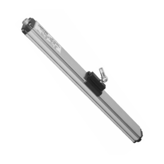
Chapter 1: Hardware Overview Chapter 1: Hardware Overview The Series 955QD Brik with Quadrature Output is an accurate, auto-tuning, non-contact, linear displacement transducer in an economical, low prole package. The transducer utilizes our eld proven magnetostrictive technology to give absolute position, repeatable to .01% of the programmable sensing distance. The streamlined anodized aluminum extrusion houses the sensing element and electronics. -
Page 5: Dimension Drawing For 955Qd Ldt
Chapter 1: Hardware Overview 1.1: Dimension Drawing for 955QD LDT Mounting Brackets (SD0522000) slide in the grooves on the side of the extruded housing. A standard female swivel mounting arm is When tightened down with fastening hard- provided with the slide magnet assembly. ware the mounting bracket clamps the unit For extensions and other options contact into place. -
Page 6: Chapter 2: Installing The Ldt
Chapter 2: Installing the LDT Chapter 2: Installing the LDT Mounting Instructions The Series 955QD can be mounted vertically or horizontally using SD0522000 mounting brackets. The mounting brackets slide in the grooves on the lower part of the extrusion and clamp down when tightened. It is recommended to use one mounting bracket on each end and every three feet in between. -
Page 7: Chapter 3: 955Qd Overview
Chapter 3: 955QD Overview Chapter 3: 955QD Overview 3.1: Quadrature Output A new method of interfacing magnetostrictive transducers offers customers an interface as common as analog with the speed and accuracy of pulsed type signaling. The Gemco 955QD LDT provides quadrature output directly from the transducer to the controller (see drawing below). - Page 8 Chapter 3: 955QD Overview The TTL level threshold signals are activated when these inputs exceed the typical TTL level threshold, which is 2.0VDC. Additionally, for the 24VDC level signals, the customer can specify either a “sourcing” or “sinking” type of input.
-
Page 9: Quadrature Output Resolution And Speed
Chapter 3: 955QD Overview 3.3: Quadrature Output Resolution and Speed The internal resolution of the 955QD Gemco LDT is 0.001”. This would be represented to the encoder input device by specifying an output resolution of 1,000 cycles per inch for the transducer. Although the typical resolution is 1,000 cycles per inch (CPI), the transducer can be ordered with virtually any CPI setting. - Page 10 Chapter 3: 955QD Overview CONNECTOR PLUG - EXPLODED VIEW P/N: SD0527700 10 PIN CONNECTOR (AS VIEWED AT SOLDER SIDE 4X SIZE CABLE CONN. WIRE COLOR PIN DESIG. BLACK GREEN BROWN BLUE ORANGE YELLOW WHITE VIOLET GRAY Figure 3-2: Power Supply Wiring Installation, Programming and Maintenance Manual...
- Page 11 Chapter 3: 955QD Overview Series 955QD Wiring Diagram CABLE ASSY P/N SD0527700L* * - LENGTH IN FEET PIN - 1 BLACK COMMON PIN - 2 POWER + PIN - 3 GREEN PIN - 4 BROWN PIN - 5 BLUE 955QD LDT PIN - 6 ORANGE PIN - 7...
- Page 12 Chapter 3: 955QD Overview CABLE ASSY. P/N SD0527700LXX TYPICAL SOURCING OUTPUT INTERFACE VSOURCE PIN-2 955QD POWER SUPPLY 10 TO 30V ZERO VIOLET PIN-9 BURST PIN-8 WHITE COMMON PIN-1 BLACK INPUT CONNECTION FOR 955QD LDT WITH SINKING INPUT CABLE ASSY. P/N SD0527700LXX TYPICAL SINKING OUTPUT INTERFACE ZERO...
- Page 13 Chapter 3: 955QD Overview CABLE ASSY. P/N SD0527700LXX TYPICAL DIFFERENTIAL INTERFACE PIN-5 BLUE PIN-6 ORANGE 955QD PIN-7 YELLOW PIN-10 GRAY PIN-3 GREEN Rt * PIN-4 BROWN Note: Rt is the termination resistor typically used for RS-422 differential POWER connections. If these termination PIN-2 VSOURCE SUPPLY...
-
Page 14: Features
Chapter 3: 955QD Overview 3.5: Features Automatic Gain Control The Automatic Gain Control feature is only used when sensing a magnet other than the standard SD0521800 slide magnet. If you are using the standard slide magnet, skip this operation. When using the Floating Magnet assembly (SD0522100), the magnet should be installed within 3/8” of the sensing surface. - Page 15 Chapter 3: 955QD Overview Burst Mode This feature enables the system to be absolute even though data transfer is through “incremental” method. In the event of power failure, the controller can be programmed to automatically send a signal to the probe, which will then respond with the current position data.
- Page 16 Chapter 3: 955QD Overview 3.6: 955QD Frequency or Pulse Rate Selecting the proper frequency in the LDT’s part number is very important. The internal clock inside of the 955QD interrogates the LDT approximately every 1 millisecond on LDT’s less than 60” in length and approximately every 2 milliseconds on the units greater than 60”...
-
Page 17: Troubleshooting For 955Qd
Chapter 3: 955QD Overview 3.7: Troubleshooting for 955QD Troubleshooting describes common problems that may occur when installing the LDT and offers possible solutions to these problems. If, after reading this appendix, you are unable to resolve a problem, contact our technical support department at 248-435-0700. - Page 18 Chapter 3: 955QD Overview If reading is between 10 and 30 VDC, turn power supply off and go to step 7. If reading is below 10 VDC, either your power supply is not providing enough power or the LDT’s cable possibly has a short/open.
-
Page 19: Catalog Numbering System For 955Qd
Chapter 3: 955QD Overview 3.8: Catalog Numbering System for 955QD 955QD 0120 1000 The Series 955QD The Brik with Quadrature Output Stroke in Inches Insert stroke in inches to 0.1 inch. Enter as a four- place number. Example: 12.0 in stroke entered as 0120. -
Page 20: SpeciCations For 955Qd
Chapter 3: 955QD Overview 3.9: Specications for 955QD General Specications: Null Zone 3.00” Dead Zone 1.50” Extrusion Assembly Anodized Aluminum with gasket seals, IP 67 Connector HRS-Style Standard (quick connect/disconnect) Connector Sensor Length Up to 14’ Agency Approval Shock and Vibration Random Vibration MIL-STD 810E, 10Grms random, 20Hz - 2K Hz Shock... -
Page 21: Accessories
Chapter 3: 955QD Overview Digital Input 1. Zero position set: 5 - 30 volts Source or Sink 2. Burst mode input: 5 - 30 volts Source or Sink Input impedance: 5 K ohms Sink threshold: Input <0.41* Power Supply Voltage i.e. -
Page 22: Glossary
Glossary Glossary Active Stroke Area The area on the extrusion between the Null and Dead Zone on which the magnet assembly moves. Burst Input An input signal to the probe will cause a “burst” of data, representing the absolute position to be fed to the controller. Dead Zone An area usually 1.5”... - Page 23 Notes: Installation, Programming and Maintenance Manual...
- Page 24 1080 North Crooks Road • Clawson, MI 48017 800-635-0289 • 248-435-0700 • Fax: 248-435-8120 955QD.M1R 06/01 • Z142 www.ametekapt.com • www.ametek.com...
Need help?
Do you have a question about the Gemco Brik 955QD Series and is the answer not in the manual?
Questions and answers