
Related Manuals for Ametek Gemco 953 Series


Summary of Contents for Ametek Gemco 953 Series
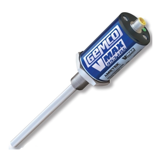
- Page 1 Series 953 Series 956 NSTALLATION ANUAL INEAR ISPLACEMENT RANSDUCERS 953A VMAX ™ Linear Displacement Transducer ABSOLUTE PROCESS CONTROL KNOW WHERE YOU ARE... REGARDLESS...
-
Page 2: Table Of Contents
All rights to the contents of this manual are reserved by Ametek. VMAX is a registered trademark of Gemco. The 953A VMax LDT with a 4 to 20mA output offers a unique diagnostic capability. The normal 4 to 20mA... - Page 3 Figure 1-1 953A Dimension Drawing ® 1080 N. Crooks Road • Clawson, MI 48017 • 800.635.0289 • Phone 248.435.0700 • Fax 248.435.8120 • www.ametekapt.com AUTOMATION & PROCESS TECHNOLOGIES...
-
Page 4: Chapter 2: Installing
Chapter 2: Installing the LDT If a mounting bracket or other part is used that is with LDTs having a rod 30”-71” in length. Supporting made of ferromagnetic material (a material readily the end of the rod will minimize operational errors and magnetized), it should be placed no closer than 0.25"... - Page 5 .2 8 2.00 2 PLACES 1.25 .28 X 1.03 SLOT .3 7 .4 4 1.00 1.00 NUL L STROK E DEAD BAN D PROBE MOUNTING KI T 1.03 (P/N 949003) OPTIONA MAGNE T 2.00 2.00 3/4-16 JAM NUT SUPPLIED W/PROB E PROB E 1.75 HE X OPTIONAL...
- Page 6 • An O-ring is provided at the base of the LDT’s If the leading edge of the magnet will come closer mounting hex for pressure sealing. The O-ring seal than 2.0” from the base of the LDT’s hex head was designed to meet Mil-Std-MS33656. Refer to when the piston rod is fully retracted, it will be SAE J514 or SAE J1926/1 for machining of mating necessary to counterbore the magnet assembly...
- Page 7 S TANDARD 4-H O LE MA G NET 0.5” BORE MINIMUM O-RING SEAL MAGNET SPACER O PTI O NAL R O D B US HIN G Figure 2-2: Mounting LDT in a Hydraulic Cylinder 1.18 RECOMMENDE D MIN. SPOTFAC E NOTES: DIAMETER SEE NOTE 1...
-
Page 8: Chapter 3: Wiring
Chapter 3: Wiring terminal (+). The LDT cable shield should be tied to earth ground at the power supply. The LDT analog common should not be connected to earth ground and Once the LDT has been installed, wiring connections should be used for connection to interface devices can be made. - Page 9 Cable # 949011LXX Typical Wiring NOTE: XX= Length in feet Figure 3-2 shows two common methods for wiring the 953A to a customer supplied interface device, such as a PLC or panel meter. The two different methods are commonly referred to as Single Ended Input or Differential Input.
- Page 10 Figure 3-4: Wiring for Connector Figure 3-5: Wiring for Connector Option "C", Integral Cable Assembly Option "H", High Temp Integral Assembly ® 1080 N. Crooks Road • Clawson, MI 48017 • 800.635.0289 • Phone 248.435.0700 • Fax 248.435.8120 • www.ametekapt.com AUTOMATION &...
- Page 11 Cable # SD0553300LXX Cable # SD0553400LXX NOTE: XX= Length in feet NOTE: XX= Length in feet Figure 3-6: Wiring for Connector Figure 3-7: Wiring for Connector Option "B", 8 Pin DIN, Option "B", 8 Pin DIN, Current Output Voltage Output CAUTION: Pinout is different for voltage vs.
- Page 12 Cable # SD0553200LXX Cable # SD0439700LXX NOTE: XX= Length in feet NOTE: XX= Length in feet Figure 3-8: Wiring for Connector Figure 3-9: Wiring for Connector Option "E", 10 Pin MS Connector Option "M", 6 Pin DIN ® 1080 N. Crooks Road • Clawson, MI 48017 • 800.635.0289 • Phone 248.435.0700 • Fax 248.435.8120 • www.ametekapt.com AUTOMATION &...
-
Page 13: 3.4: Setting Zero & Span Position
Before programming the Zero or Span, the program 3.3: Features input must be connected to the Power Supply Automatic Gain Control Common for a minimum of 2 seconds and no more The Automatic Gain Control feature will automatically than 6 seconds, then released for 1 second. The search and find the magnet on power up, if power is LTD programming sequence is now unlocked and applied without a magnet on the LDT, the LED will turn... -
Page 14: Appendix A: Troubleshooting
Optional In-Line Programmer Optional Remote Tester & Programmer The battery operated remote tester / programmer is The 955-1409 is a remote available in either a voltage or current model. P/N programmer that can help SD0528810 is designed for voltage simplify the programming units while SD0528811 is for current units. -
Page 15: Appendix B: Part Numbering
Appendix B: Part Numbering to power the LDT. When powering more than one NOTE: LDT’s with integral cable assemblies VMAX on a single power supply, remember that each should be checked for proper voltage at the power supply terminals. This cable assembly cannot be unit requires approximately one watt of removed from the LDTIf the reading is between 7 power. -
Page 16: Appendix C: Specifications
Appendix C: Specifications General Specifications Rod End 316 Stainless Steel, 0.405" (10.29 mm) outer diameter Mounting Hex 316 Stainless Steel, 1.75" (44.45 mm) across flats, IP68 Mounting Threads 3/4" (19.05 mm) x 16 x 1.00" (25.4 mm) with ESNA jam nut and O-ring seal. Optional M 18x 1.5 Metric threads Head Assembly Thick wall aluminum cover with Viton O-ring standard, gasket seal at the base and connector exit, IP68 IEC 600529, stainless steel cover optional... - Page 17 NOTES: Part Number Serial Number Purchase Order Number Sales Order Number Comments...
- Page 18 Other Products ® Copyright 2012 by AMETEK Automation & Process Technologies. All Rights Reserved. Made in the USA. ® 1080 N. Crooks Road, Clawson, MI 48017-1097 953A.M3R Phone: 248.435.0700 Toll Free: 800.635.0289 4/12.Z191 Fax: 248.435.8120 www.ametekapt.com AUTOMATION & PROCESS TECHNOLOGIES...
Need help?
Do you have a question about the Gemco 953 Series and is the answer not in the manual?
Questions and answers