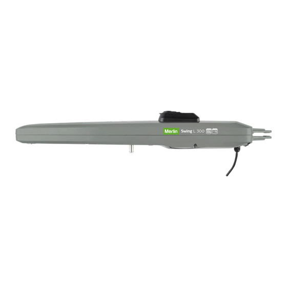
AS/NZS 60335.1 in conjunction with AS/NZS 60335.2.103. Only Merlin genuine and approved accessories may be connected to the gate opener. Incorrect installation and/or failure to comply with the following instructions may result in serious personal injury or damage to property.
Page 3
SAFETY INSTRUCTIONS During operation, the gate should not under any circumstances obstruct public path ways and roads (public area). When using tools and small parts to install or carry out repair work on a gate, exercise caution and do not wear rings, watches or loose clothing. To avoid serious personal injury due to entrapments, remove any locking device fitted to the gate in order to prevent damage to the gate.
INTRODUCTION SPECIFICATIONS – SWING L 300 – MGLSK / MGLDK / MGLSK-LV / MGLDK-LV Main AC Supply:…….…………………...……….……………..220-240 Vac; 50/60 Hz Motor Voltage: …………..…………………..………………….24 Vdc Input Power (single arm): .…………..…………………..……50 W Ambient Temperature Range: …………..…………………...-20 ~ +55˚C Maximum Weight for single Gate..…………..……………… 300 kg/2 m, 250 kg/2.5 m, 200 kg/3 m Maximum Width for single Gate ..…………..………………...1.8 m, 2.5 m Maximum Pull Force:…………………………….....………….1500 N Maximum Open Angle: …………..…………………..………..120˚...
Page 6
INTRODUCTION SALES KIT INVENTORY - MGLDK MAINS VOLTAGE 240V OR MGLDK-LV LOW VOLTAGE 24V SWING GATE OPENER LINEAR ACTUATOR DUAL KIT Your gate opener is packed in separate cartons. The Swing L 300 MGLDK or MGLDK-LV opener sales kit contains the opener, its hardware, accessories and a transformer MGTR3-120VA (only for the MGLDK-LV sales kit).
INTRODUCTION TOOLS NEEDED OVERVIEW OF THE GATE OPENER MGLSK – MAINS VOLTAGE 240V SWING GATE OPENER LINEAR ACTUATOR SINGLE KIT OR MGLSK-LV – LOW VOLTAGE 24V SWING GATE OPENER LINEAR ACTUATOR SINGLE KIT Single Swing Gate Transformer Box Remote mounted near 240V Control power supply (MGTR3-120VA)
Page 8
INTRODUCTION INSTALLING THE WARNING LABELS WARNING Warning Label is provided with each sales kit (MGLSK, MGLDK, MGLSK-LV & MGLDK-LV). The warning label must be placed on the inside of the post. Moving Gate Can Cause Serious Injury Or Death Persons are to keep clear! The gate is able to be moved without prior warning.
INTRODUCTION Before installing the gate opener, ensure that the gate is opening smoothly. Determine the dimensions based on the opening angle provided in Table 1 (below) to confirm the position where the post bracket will be mounted. Ensure that all the required cables (power cable, accessory cables etc) are prepared and laid correctly. NOTE: All crushing points must be secured by an entrapment protection according to AS/NZS 60335.1 in conjunction with AS/NZS 60335.2.103.
Page 10
INTRODUCTION DETERMINE THE POSITION OF THE POST BRACKET Determine the A and B dimension in base on the opening angle provided in Table 1 to confirm the position where the post bracket will be mounted. The max dimension for C, should be the B dimension minus the 60mm (refer to the tables below). For optimal mechanical advantage A and B dimension shall be equal or close.
INSTALLATION POST BRACKET INSTALLATION Using the fixed post bracket as a reference, mark and drill the holes for the post bracket. Attach the post bracket to the post using appropriate fixings. Masonry fixings are supplied, if required. The correct fastening material must be used based on existing installation (building / material substance).
INSTALLATION HARD STOPS INSTALLATION Release the opener manual release with the release key. See section 11. Using the internal opener hardstops to adjust the gate’s travelling distance, loosen each of the adjustment screws with a 5mm Allen key. Move the gate to the desired close position and reposition the hardstop to suit and secure the hardstop with a 5mm Allen key (not supplied).
INSTALLATION INSTALL THE CONTROL BOX The control box must be installed at a safe location that enables the installer to have access at all times to the logic board without the risk of the gates crushing or trapping. It is advised that you must have full view of the gates when programming the logic board. Install the control box in an appropriate and accessible position.
WIRING ELECTRICAL SAFETY To reduce the risk of SEVERE INJURY or DEATH: • BEFORE installing the power wiring or control stations be sure to follow all specifications and warnings. Failure to do so may result in SEVERE INJURY to persons and/or damage to the opener. •...
INSTALL ENTRAPMENT PROTECTION DEVICES THE PROTECTOR SYSTEM™ (IR BEAMS) (OPTIONAL) NOTE: Merlin strongly recommends that The Protector System™ (IR Beams) be installed on all gate openers. Compatible Protector System™ (IR Beams) are 772ANZ and GPS15 Monitored Safety Beams. The Protector System™ (IR Beams) can be configured to function differently when connected to IR1, IR2 or IR3 inputs.
PROGRAMMING LCD SCREEN MENU Programming buttons function (4 buttons): Button Function Program / delete remote controls and specific functions Enter programming mode, select function and save. NOTE long press of P button will save the setting and exit out to the menu screen.
Page 18
PROGRAMMING OVERVIEW Legend Function Section Application Opener Motor Type Direction Motor 1 Direction Motor 1 Direction Motor 2 Direction Motor 2 Learning Limit & Force Learn Remote Control Behaviour Adjust the behaviour of remote controls IR1-Behaviour Adjust the behaviour of Protector System Safety IR Beams in input IR 1 Adjust the behaviour of Protector System Safety IR Beams in input IR 2 IR2-Behaviour IR3-Behaviour...
PROGRAMMING INITIAL SETUP figure 1 Energise the opener. Release the opener manual release with the key, and move the gate(s) to a mid open position. Re-engage the manual release. CYCLES: 000, 000 MAIN MENU BEGIN SETUP SELECT The LCD screen will display the Cycle count. APPLCATION Press and hold the “P”...
BASIC SETTINGS LIMIT AND FORCE LEARNING figure 1 figure 2 Within the Basic Setting, navigate through the menu screen MAIN MENU LIMIT & FORCE LEARN until you find “MAIN MENU LIMIT & FORCE LEARN”. LIMIT & FORCE LEARN INTERRUPTED Press the “P” button to enter this setting (figure1). The menu screen will begin flashing “LIMIT &...
BASIC SETTINGS INPUT COMMAND Within the Basic Setting, navigate through the menu screen until you find “MAIN MENU INPUT 1”. figure 1 Press the “P” button to enter this setting (figure 1). Press the “+” or “-“ buttons to navigate through the options. MAIN MENU You can select the following options: INPUT 1...
BASIC SETTINGS DELAY MOTOR 1 IN CLOSE DIRECTION Within the Basic Setting, navigate through the menu screen until you find “MAIN MENU DELAY MOTOR 1 - CLOSE”. figure 1 Press the “P” button to enter this setting (figure 1). Press the “+” or “-“ buttons to navigate through the options. MAIN MENU You can have no delay, or select delays from 1 second to 20 seconds.
BASIC SETTINGS REVERSAL TIME Within the Basic Setting, navigate through the menu screen until you find “MAIN MENU figure 2 figure 1 REVERSAL TIME”. MAIN MENU Press the “P” button to enter this setting 2 SECOND REVERSAL (figure 1). REVERSAL TIME Press the “+”...
BASIC SETTINGS RAM BLOW MOTOR 1 FOR E-LOCK Within the Basic Setting, navigate through the menu screen until you find “MAIN MENU RAM-BLOW". figure 1 Press the “P” button to enter this setting (figure 1). Press the “+” or “-“ buttons to navigate through the options. MAIN MENU You can select the following options: RAM-BLOW...
BASIC SETTINGS SPECIAL CONTACT Within the Basic Setting, navigate through the menu screen until you find “MAIN MENU SPECIAL CONTACT RELAY". Press the “P” button to enter this setting (figure 1). Press the “+” or “-“ buttons to navigate through the options. You can select the following options: figure 1 •...
ADVANCED SETTINGS If the Default speed and force values are changed in the Advanced Settings, the force reversal behaviour of the gate opener may be affected. Additional safety devices must be used for installations where the force measured on the leading edge of the gate in both the open and close direction is over 400N. Installers must ensure that the gates are installed in a compliant manner as per AS/NZS 60335.2.103.
ADVANCED SETTINGS PASSWORD ENTER PASSWORD figure 1 figure 2 Navigate the Menu screen till you get to “MAIN MENU PASSWORD” by pressing the SET PASSWORD “+” and or “-” buttons (figure 1). MAIN MENU ENTER PASSWORD Press the “P” button to enter this setting PASSWORD (figure 1).
ADVANCED SETTINGS SPEED MOTORS 1 AND 2 IN OPEN DIRECTION (PASSWORD PROTECTED) NOTE: To access this setting the password must be entered. figure 1 Within the Advance Setting, navigate through the menu screen until you find “MAIN MENU SPEED-MOTOR 1 & 2 OPEN (PW)”. MAIN MENU SPEED-MOTOR 1 &...
FACTORY RESET FACTORY RESET Within the Advance Setting, navigate through the menu screen until you find “MAIN MENU FACTORY RESET”. Press the “P” button to enter this setting (figure 1). Press the “+” or “-“ buttons to navigate through the options. figure 1 You can select the following options: •...
WIRELESS PROGRAMMING REMOTE CONTROL PROGRAMMING Activate the opener only when the gate is in full view, free of obstruction and properly adjusted. Do not allow children to operate push button(s) or transmitter(s). Do not allow children to play near the gate. NOTE: The transmitter(s) supplied with your opener are preprogrammed by the factory.
How To Connect The Merlin Gate Opener: Scenario 1: If the homeowner currently already has a Merlin gate opener or other device that is connected to the myQ App via a myQ® gateway accessory, the homeowner will need to: • Purchase a Merlin gate opener that is myQ compatible (the latest range of Merlin gate openers are all myQ compatible) •...
Page 32
B. Installation Process • Gate Opener: Install the Merlin Gate Opener to a fully functional gate using the installation instructions included in this manual. • Protector System (Safety IR Beams) 772ANZ or GPS15 Reflector Safety IR Beams: Install the Protector System (Safety IR Beams) 772ANZ supplied with the gate myQ Connectivity Kit or as an individual accessory.
Page 33
WIRELESS PROGRAMMING MYQ SETUP – MYQ GATEWAY INSTALLATION (OPTIONAL) CONTINUED Step 2 – Register The myQ Gateway & Add Devices Once you have successfully created your myQ® account, you must add the myQ® Gateway to the account. It is easy to do from your Internet enabled smartphone or tablet.
OPERATION AND MAINTENANCE ERROR CODES To reduce the risk of SEVERE INJURY or DEATH: • Disconnect ALL power BEFORE performing ANY maintenance. • ALL maintenance MUST be performed by a professional installer. • ALWAYS wear protective gloves and eye protection when changing the battery. •...
OPERATION AND MAINTENANCE ERROR CODES Error Problem Action Required How to Clear ERR: • PCB has detected a • Power down the gate operator for 20 seconds. • Power down for 20 MOTOR1 motor failure seconds and power on • Once the gate has been powered up again, to reset.
PROGRAMMING FLOW CHART BASIC SETTINGS - PART 1 Main Menu 1st - Select 2nd - Direction 3rd - Direction 4th - Limit & Force 5th - Exit ( & Save) Motor/Application Motor 1 Motor 2 Learn Press & Hold '+' Press &...
Page 38
PROGRAMMING FLOW CHART BASIC SETTINGS - PART 2 Main Menu Pedestrian Delay Motor 2 Remote Control IR 1 / 2 / 3 Input 1 / 2 / 3 Opening - Open Behaviour Behaviour Behaviour Open - Close - Open - Close - IR1/2/3 CLOSE No Delay Open...
Page 39
PROGRAMMING FLOW CHART BASIC SETTINGS - PART 3 Main Menu Delay Motor 1 Reversal TIme Timer -To-Close E - Lock Flashing Light - Close Open/Close 2 Second TTC Disabled No Delay Disabled Disabled Reversal 1 Second Setting TTC E-Lock, Reversal to Continuous Delay 10 Seconds...
Page 40
PROGRAMMING FLOW CHART BASIC SETTINGS - PART 4 Main Menu Special Contact Maintenance Soft & Hard Start Pre Flashing Relay Setting Counter Soft & Hard Start Disabled Disabled Disabled Setting Soft Start 15 Seconds 1 Second 1000 Cycles Enabled Hard Start 30 Seconds 2 Seconds 2000 Cycles...
Page 41
PROGRAMMING FLOW CHART ADVANCED SETTINGS Advance Settings - Fine tuning force, speed and delay settings. Note percent value is relative to learned value e.g. ‘increase 15%’ is a 15% increase over the learned setting. Main Menu Password Protected Speed-Motor Speed-Motor Soft Stop Force Motor Factory Default...
Page 42
WARRANTY DON’T FORGET Warranty Registration To validate your warranty you must complete the registration form online at: gomerlin.com.au/warranty gomerlin.co.nz/warranty Get Connected with Additional purchase of the myQ Connectivity Kit is required to enable myQ functionality. Visit www.gomerlin.com.au or www.gomerlin.co.nz for more details. Trademark of The Chamberlain Group, Inc.
You are also entitled to have the goods repaired or replaced if the goods fail to be of acceptable quality and the failure does not 3 use of any copy, imitation or replica gate opener remotes with your Merlin Unit; amount to a major failure.
Need help?
Do you have a question about the Swing L300 and is the answer not in the manual?
Questions and answers